Advertisement
Quick Links
Download this manual
See also:
Operating Manual
VAM150FC
VAM250FC
INSTALLATION MANUAL
Total Heat Exchanger
HRV (Heat Reclaim Ventilation)
(Ceiling mounted duct type)
Unité HRV (unité de ventilation avec récupération de chaleur)
HRV (Heat Reclaim Ventilation of Hergebruik van warmte)
(Type voor plafondmontage met kanaalaansluiting)
HRV (ventilazione con recupero di calore)
(Tipo canalizzato per installazione sul soffitto)
HRV (∞Ó¿ÎÙËÛË £ÂÚÌfiÙËÙ·˜ ∞ÂÚÈÛÌÔ‡)
HRV (Ventilação de Recuperação Térmica)
HRV (Вентиляция с регенерацией тепла)
Total Heat Exchanger
HRV (Heat Reclaim Ventilation)
(Ceiling mounted duct type)
Gesamt-Wärmetauscher
HRV (Wärmerückgewinnungslüftung)
(Kanal zur Deckenmontage)
Echangeur de chaleur totale
(Type montée au plafond à canalisations)
Warmtewisselaar
Intercambiador de Calor Total
HRV (Ventilación de Reclamo de Calor)
(Tipo de conducto montado en el techo)
Scambiatore di calore totale
∂Ó·ÏÏ·ÎÙ‹˜ Û˘ÓÔÏÈ΋˜ ıÂÚÌfiÙËÙ·˜
(∞ÂÚ·ÁˆÁfi˜ ÔÚÔÊ‹˜)
Permutador Térmico Total
(Tipologia em conduta montada no tecto)
Инверторный кондиционер системы
(Потолочный воздуховод)
English
Deutsch
Français
Nederlands
Español
Italiano
EÏÏËÓÈο
Portugues
русский
Advertisement

Subscribe to Our Youtube Channel
Related Manuals for Daikin VAM250FC


Summary of Contents for Daikin VAM250FC
- Page 1 (Tipo canalizzato per installazione sul soffitto) ∂Ó·ÏÏ·ÎÙ‹˜ Û˘ÓÔÏÈ΋˜ ıÂÚÌfiÙËÙ·˜ EÏÏËÓÈο HRV (∞Ó¿ÎÙËÛË £ÂÚÌfiÙËÙ·˜ ∞ÂÚÈÛÌÔ‡) (∞ÂÚ·ÁˆÁfi˜ ÔÚÔÊ‹˜) Permutador Térmico Total Portugues HRV (Ventilação de Recuperação Térmica) (Tipologia em conduta montada no tecto) Инверторный кондиционер системы VAM150FC HRV (Вентиляция с регенерацией тепла) русский (Потолочный воздуховод) VAM250FC...
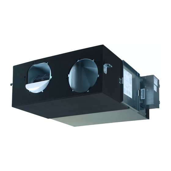
- Page 2 VAM150F VAM250F ø200...
- Page 3 2P333093-2A...
-
Page 4: Table Of Contents
fire or other damage to the equipment. Be sure only to use accessories, optional equipment and spare parts made by Daikin which are specially designed for use with the products as of subject in this manual and have them installed by an installer. -
Page 5: Dimensions
Example of Installation (See figure IMENSIONS Air suction/discharge grille (option) (See figure Inspection hole 450 mm (field supply) Maintenance space for the heat exchange elements, air filters and Maintenance space for the heat exchange elements, air filters and fans fans Maintenance cover Duct (field supply) Inspection hole... - Page 6 Method of installation Duct connection Do not connect the ducts as follows Extreme bend Multi bend Do not bend the duct over 90° Screw (accessories) Duct connecting flange (accessories) Reduce the diameter of the duct to be connected. Installation of duct connecting flanges Do not reduce the duct diameter halfway.
-
Page 7: System
YSTEM Independent system Air conditioner linked operation system Related items in System Standard method Electric wiring • Up to 16 units can be controlled with the remote controller for HRV. (A system with two remote controls can be created in the master/slave switching.) •... - Page 8 Centralized control system (VRV system) Related items in System Standard method Electric wiring • Use of the on/off controller, Adapter PCB for remote control schedule timer enables centralized control of the entire system. (maximum of 64 groups) • The on/off controller can turn on or off the individual units.
-
Page 9: Electric Wiring
LECTRIC WIRING Component electrical specifications 150F 250F Before obtaining access to terminal devices, all power Units supply circuits must be interrupted. Type JVE, 5VE 50 Hz Power supply Max. 264 V/Min. 198 V 60 Hz Power supply Max. 242 V/Min. 198 V Connection of wiring Power supply Connect the wires in accordance with the diagram of each... - Page 10 View seen from VRV Wiring example P1 P2 F1 F1 T1 T1 P2 P1 F1 F2 J2 JC Terminal board for transmission wiring Terminal board for power supply Grounding terminal Power supply wiring Clamp material (attached) Remote controller wiring Unit wiring Field supply wire/Earth terminal (attached) Ground the shield part of shielded wire.
- Page 11 Opening the switch box Required electrical connections for possible additional field supplied external damper CAUTION The external damper prevents the intake of outdoor air if the HRV is Before opening the cover, be sure to turn off the power switched off. (Refer to figure 2, item 19). switches of the main units and other devices connected The HRV's main unit PCB operates the HRV and supplies power with the main units.
- Page 12 How to install the optional adapter circuit board How to install the optional heater control kit (BRP4A50) (KRP2A61, KRP50-2) When operating the HRV units at or below –10°C of the outdoor air temperature, use a field supplied preheater to preheat outdoor air. When installing the optional adaptor circuit board, it is necessary to prepare the fixing box (KRP50-2A90) The BRP4A50 kit is required to have an ON/OFF delay control when...
- Page 13 Power cord connection, control wire terminals and switches Local setting on the electronic control unit (printed circuit board) Using the remote controller of the VRV-system air conditioner to Connect the power cord to the L and N terminals. make HRV unit settings Secure the power cord with the power cord clamp, as shown in Initial setting "Opening the switch box"...
- Page 14 Example When adjusting the ventilation air flow to low setting in the group setting mode, enter the mode No., "19" setting switch No., "0" and setting position No., "01". List of Settings Mode No. Setting position No.(Caution *1.) Group Individual Setting settings settings...
- Page 15 For "FRESH UP" operation, Operation with the remote control exclusively for Air • If it is set to "Fresh up air supply": The volume conditioning operation HRV units. (BRC301B61) of outdoor air supplied into the room is larger than that of room air exhausted outdoors. For non-independent systems, starting/stopping operation and timer (This operation prevents the odour and operation may not be possible.
- Page 16 Wiring and connections in combination with 12. Push the button " " and set the time. "VRV-SYSTEM" Each time when " " is pushed, the time advances one hour. Standard 1-group linked-control system Each time when " " is pushed, the time goes back one hour. The remote control of the air conditioner can be used to control 13.
- Page 17 Connecting the remote controller for HRV Direct duct connection system for 1-group operation system The remote controller for HRV cannot be used for starting/stopping operation or for timer operation. (The centralized control indication Line connections and the settings of the switches on the HRV unit will be lit.) PCB should be the same as for "Standard system for 1-group system".
- Page 18 Procedure The Adapter PCB for remote control and schedule timer cannot be used together. Turn off the main power. The Adapter PCB for remote control can be mounted on the Connect the air-conditioner remote controller. electric component mounting base of either the HRV unit or air conditioner.
- Page 19 Procedure A maximum of 64 air conditioners and HRV units can be connected to the F1 and F2 terminals. Turn off the main switch of the HRV-1 and On/off controller. The HRV units will turn on and off in according with the zone Connect the air conditioner's remote controller.
-
Page 20: Test Run
OTES Fresh-up operation Purposes When combined with a local ventilating fan (such as the one in toilet and kitchen), the air flow rate of HRV is balanced by either fan operation or exhaust operation. However, a circuit with voltage and low current (16 V, 10 mA) is formed between JC and J1, so a relay with low-load contact point must be used. -
Page 21: Wiring Diagram
IRING DIAGRAM Power supply Single phase 220-240/220 V External output terminals 50/60 Hz Adapter for wiring (optional accessories) (KRP50-2) Terminals for the input front outside Terminals for the centralized control Remote controller (Optional accessories) L-RED N-BLU NOTE Terminals Printed circuit board Wire clamp C1R-C2R Capacitor (M1F•M2F) - Page 22 NOTES...
- Page 23 NOTES...
- Page 24 4P415946-1 2015.08...
Need help?
Do you have a question about the VAM250FC and is the answer not in the manual?
Questions and answers