Table of Contents
Advertisement
Quick Links
Echoflex Installation Guide
Emergency Bypass Load Controller EREB
Overview
The Emergency Bypass Load Controller (EREB) is powered by an
emergency source to provide power to emergency lighting loads. The
EREB ensures the emergency lighting is on during loss of circuit power,
and also tracks the state of controlled lighting loads during normal
operation. The EREB ensures a "lights on" override by using a normally
closed emergency contact closure that interfaces with fire alarm and
emergency systems.
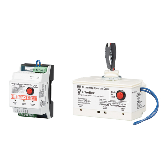
The EREB is available in two models to provide installation options: Power
Pack EREB-AP and DIN rail EREB-AD.
Power Pack: EREB-AP
This document covers installation of all the EREB models. The product
package includes the controller and lock nut for the EREB-AP model.
Electrical Specifications
Certified by UL and cUL listed Emergency Lighting and Power
•
Equipment under UL 924 at 120 and 277 VAC line voltages, 60 Hz.
Ballast load rating: 20 A maximum at 120 or 277 VAC.
•
Incandescent load rating: 10 A maximum at 120 or 277 VAC.
•
UL 2043 Plenum rated, EREB-AP model only.
•
Provides remote activation by dry contact closure for connection to a
•
fire alarm or building management system.
Provides auxiliary contact for 0–10 VDC or fluorescent ballasts,
•
EREB-AD model only.
Corporate Headquarters n Middleton, WI, USA | +1 608 831 4116
Web
echoflexsolutions.com
©2022 Echoflex Solutions, Inc. Trademark and patent
Product information and specifications subject to change.
Echoflex intends this document to be provided in its entirety.
8189M2133 Rev A Released 2022-09
| Email
info@echoflexsolutions.com
DIN rail: EREB-AD
| Support
service@echoflexsolutions.com
info: echoflexsolutions.com/ip
Advertisement
Table of Contents

Related Manuals for echoflex EREB-AP


Summary of Contents for echoflex EREB-AP
- Page 1 Power Pack: EREB-AP DIN rail: EREB-AD This document covers installation of all the EREB models. The product package includes the controller and lock nut for the EREB-AP model. Electrical Specifications Certified by UL and cUL listed Emergency Lighting and Power •...
-
Page 2: Important Safeguards
Echoflex Installation Guide Emergency Bypass Load Controller IMPORTANT SAFEGUARDS READ AND FOLLOW ALL SAFETY INSTRUCTIONS WARNING: RISK OF ELECTRIC SHOCK! This device utilizes high voltage and should only be installed by a qualified installer or electrician. Follow all local codes for installation. Before terminating the AC power wiring verify... -
Page 3: Installation
Model EREB-AP Ensure that the junction box is clean and free of obstructions and that all wiring is installed correctly. The EREB-AP mounts directly to the exterior of the junction box or panel, either at the electrical lighting load or before the loads in the circuit. - Page 4 Button Remote Activation Input The EREB-AP offers a normally closed, dry contact input to accommodate connection to a fire alarm panel, security system, or test switch. This input ships from the factory with a blue wire loop (jumper) on the side of the device.
- Page 5 The remote device that triggers the Emergency circuit ON must provide a normally closed, maintained dry contact closure for fire alarms. When the remote device is activated, the contact closure opens and the contacts force the EREB-AP into the emergency ON state. Note: When using 1 mm...
- Page 6 Echoflex Installation Guide Emergency Bypass Load Controller 4. Connect the normal lighting circuit to the Normal Power Sense, Normal Switch Sense, and Normal Neutral screw terminals. Note: To ensure that the emergency lighting connected to the device turns On in the event of a power loss, the Normal Power Sense wire must be connected upstream of any switched control device for the normal lighting loads.
- Page 7 Do not remove this jumper unless you are installing a remote triggering device. Note: Echoflex recommends that you power up and test your system before connecting to a remote device. Do not remove the jumper unless you are installing a remote triggering device.
-
Page 8: Initial Test
Initial testing of the EREB should be done with the Remote Loop In and Remote Loop Out jumper installed on the EREB-AD and the blue loop uncut on the EREB-AP. 1. Turn On the circuit breaker in the emergency panel for the controlled circuit. - Page 9 Echoflex Installation Guide Emergency Bypass Load Controller What does the Test button do? EREB-AP: [Test] button simulates the loss of normal power and • bypasses the normal switching of power to the fixture. When using the EREB-AP with a directly-controlled emergency fixture containing a control input (for example, 0–10 V or DMX), note that the [Test]...
-
Page 10: Examples Of Use
Echoflex Installation Guide Emergency Bypass Load Controller Examples of Use Switch Control Arrangement When normal power is present, the switch controls both the normal • and emergency light fixtures. When the normal power is lost, the emergency light fixture turns ON •... - Page 11 Echoflex Installation Guide Emergency Bypass Load Controller Phase Dimmer Control When normal power is present, the emergency fixture behaves as a • normally controlled fixture. When the normal power is lost, the emergency fixture turns ON full. • Emergency Neutral (Gray) Emerg.
- Page 12 Echoflex Installation Guide Emergency Bypass Load Controller Compliance For complete regulatory compliance information, see the Echoflex Emergency Bypass Load Controller datasheet at echoflexsolutions.com. FCC Compliance Echoflex Emergency Bypass Load Controller (For any FCC matters): Echoflex Solutions, Inc. 3031 Pleasant View Road...
Need help?
Do you have a question about the EREB-AP and is the answer not in the manual?
Questions and answers