Table of Contents
Advertisement
Quick Links
Echoflex Installation Guide
Tunable White Dimming Controller
Overview
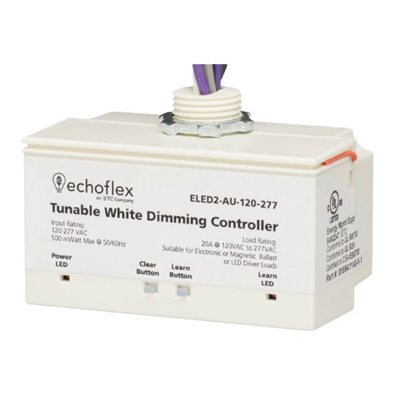
The ELED2 Tunable White
Dimming Controller includes two
output channels of 0-10 V to
control light intensity and color
temperature levels for a single
compatible fixture or an entire
zone. It also supports external
setpoint input from a gateway or
outdoor CCT sensor.
This document covers installation
of ELED2 Tunable White Dimming
Controller models. The Echoflex
Tunable White Dimming
Controller ELED2 Configuration
Guide is available for download at echoflexsolutions.com.
The package contents includes the controller and the installation guide.
Prepare for Installation
Echoflex recommends paying special attention to the installation
environment.
• High density construction materials and large metal appliances or
fixtures in the space may disrupt wireless reception.
• Mount the controller to an electrical junction box or a panel in a
location and at a height where it is not subject to tampering by
unauthorized personnel.
Supplies required to install the controller (not provided):
• Appropriately sized wire nuts
• Wire insulation
• Small cable ties
Corporate Headquarters Middleton, WI, USA
Web
echoflexsolutions.com
© 2021 Echoflex Solutions, Inc. Trademark and patent info:
Echoflex intends this document to be provided in its entirety. Product information and specifications subject to change.
8189M2111 Rev A Released 2021-03
|
Phone +1 608 831 4116
|
Email
info@echoflexsolutions.com
|
Support
support.etcconnect.com
echoflexsolutions.com/ip
High voltage
model shown
Advertisement
Table of Contents

Related Manuals for echoflex ELED2


Summary of Contents for echoflex ELED2
- Page 1 Phone +1 608 831 4116 echoflexsolutions.com Email info@echoflexsolutions.com Support support.etcconnect.com © 2021 Echoflex Solutions, Inc. Trademark and patent info: echoflexsolutions.com/ip Echoflex intends this document to be provided in its entirety. Product information and specifications subject to change. 8189M2111 Rev A Released 2021-03...
-
Page 2: Important Safeguards
Echoflex Installation Guide Tunable White Dimming Controller IMPORTANT SAFEGUARDS READ AND FOLLOW ALL SAFETY INSTRUCTIONS WARNING: Risk of electric shock! This device utilizes high voltage and should only be installed by a qualified installer or electrician. Follow all local codes for installation. Before... -
Page 3: Installation
Echoflex Installation Guide Tunable White Dimming Controller Installation All local codes and standard electrical practices should be observed. Ensure that the junction box is clean and free of obstructions and that all wiring is installed correctly. Note: Follow applicable NEC and local electrical code requirements when installing and powering the controller. -
Page 4: Wiring Diagram
Analog Color control Violet with Green stripe CCT 0-10 V Control - 100 mA MAX sinking current Max. Switching Load (ELED2) 20 A @ 120-277 VAC, Electronic Ballast or LED Driver (ELED2H) 20 A @ 240-277 VAC, Electronic Ballast or LED Driver Tunable White Dimming Controller (ELED2H) 16 A @ 347 VAC, Electronic Ballast or LED Driver Max. - Page 5 Electrical Terminations Power to the controller is connected between the White (Neutral) and the Black Line power: ELED2 (120-277 VAC) or ELED2H (240–347 VAC). The Class 1 power limited dimming lines (violet with red stripe wires) is used to provide 0–10 V intensity control of a dimming ballast or LED driver. The orange wire is an antenna.
-
Page 6: Controller Interface
2. Release the [Clear] button. The Power LED displays solid red to indicate factory default state. All links are removed. Test the Controller Echoflex provides the controller in either a pre-commissioned state or a factory default state. • Pre-commissioned devices are linked, configured, and labelled according to customer specifications. - Page 7 Echoflex Installation Guide Tunable White Dimming Controller Operations page 7. To test the relay(s), press the [Learn] button or use a linked switch. • In factory default state, when powered up, the Power LED displays solid red to indicate the controller has no linked devices. To test the relay(s), press the [Learn] button or link a switch.
- Page 8 On solid (on power-up) Compliance and Listings For complete regulatory compliance information, see the Echoflex Tunable White Dimming Controller datasheet at echoflexsolutions.com. FCC Part 15.231 Contains FCC ID: SZV-STM300U This device complies with part 15 of the FCC rules. Operation is subject to the following two conditions: (1.) this device may not...
Need help?
Do you have a question about the ELED2 and is the answer not in the manual?
Questions and answers