Table of Contents
Advertisement
Quick Links
A4964 Sensorless Sinusoidal Drive BLDC Controller
Introduction
This user manual describes the operation and use of the
APEK4964 evaluation board for the A4964 automotive,
programmable BLDC controller. The A4964 is a flexible
sensorless, sinusoidal motor controller that drives an external
three-phase N-channel MOSFET bridge for easy implemen-
tation of a BLDC motor driver. The A4964 can be used as
a standalone controller or it can be used in a system with a
microcontroller, providing communication to a central ECU
and intelligent fault and status handling. The A4964 can
provide the supply and watchdog for the microcontroller,
as well as a physical interface between a LIN bus network
or a supply level PWM signal and the microcontroller. The
A4964 can be easily put to sleep or woken up using software
commands or signal inputs. In the sleep state, the power
consumption can be reduced to a low level.
The motor can be driven using a number of modulation
options, from full three-phase sinusoidal drive to two-phase
trapezoidal drive and includes overdrive options in the sinu-
soidal mode.
Commutation between the phases is independent of any
position sensor and rotor position detection is achieved by
monitoring the motor back-emf (bemf). The integrated sen-
sorless startup scheme provides highly programmable startup
options, allowing the A4964 to operate over a wide range of
motor and load combinations. It also includes forward and
reverse pre-rotation (windmill) detection and synchroniza-
tion.
Several operational modes are available, including duty-
cycle (voltage) control, current (torque limit) control, and
closed-loop speed control. Operating mode and control
parameters can be altered through an SPI-compatible serial
interface.
Integrated diagnostics provide indication of undervoltage,
overtemperature, and power bridge faults and can protect
the power switches under most short-circuit condition. By
monitoring the contents of the status register in the A4964
via the serial interface, any fault conditions present can eas-
ily be identified.
The A4964 is fully described in its datasheet, which should
be read in conjunction with this user manual.
APEK4964-UM, Rev. 4
MCO-0001338
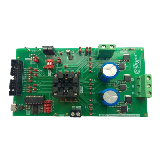
Evaluation Board User Manual
Figure 1: A4964 Evaluation Board
........................................................................... 1
......................................................... 2
.................................................... 2
.............................................................. 2
................................................................ 3
............................................................. 3
................................................................. 3
.............................................................. 4
....................................................................... 4
..................................................................... 5
.............................................................. 5
...................................................................... 6
............................................................................. 6
........................................................................ 7
.................................................................. 7
..................................................................... 8
.................................................... 10
.............................................. 10
............................................................... 10
.............................................. 10
........................................................................ 12
............................................................................. 13
............................................................................. 14
........................................................... 14
.............................................................. 14
............................................................ 15
................................................................. 15
................................................................... 15
.............................................................. 20
APEK4964
.................................... 10
.......................................... 12
........... 13
... 16
..................................... 17
.......................................... 18
.................................. 19
December 9, 2022
Advertisement
Table of Contents

Related Manuals for Allegro MicroSystems APEK4964


Summary of Contents for Allegro MicroSystems APEK4964
-
Page 1: Table Of Contents
Evaluation Board User Manual Introduction This user manual describes the operation and use of the APEK4964 evaluation board for the A4964 automotive, programmable BLDC controller. The A4964 is a flexible sensorless, sinusoidal motor controller that drives an external three-phase N-channel MOSFET bridge for easy implemen- tation of a BLDC motor driver. -
Page 2: Evaluation Board Features
X1. A positive supply, between 5.5 and 50 V, ILIM is the limitation current value. is connected to X1, labelled VBB. The supply return is labelled Allegro MicroSystems 955 Perimeter Road Manchester, NH 03103-3353 U.S.A. www.allegromicro.com... -
Page 3: Load Connections
The detailed installation guides for the hardware driver can be found through the support page on the FTDI website. “SPI Status” window will display “False!”. Allegro MicroSystems 955 Perimeter Road Manchester, NH 03103-3353 U.S.A. www.allegromicro.com... -
Page 4: Gui General Overview
In order to avoid short circuit in the phase of the power MOSFET which can be set by MIT variable, and bridge, a dead time is required between generating a low or high is the current limit scale defined by VIL. Allegro MicroSystems 955 Perimeter Road Manchester, NH 03103-3353 U.S.A. www.allegromicro.com... -
Page 5: Speed Control
LOS (shown in the content of status register in Figure 4) will flag, and the manual in the Setting Up for First Time Use section. Allegro MicroSystems 955 Perimeter Road Manchester, NH 03103-3353 U.S.A. -
Page 6: Motor Control
KM is related to the motor bemf constant and can be cal- There are three control modes in the A4964: closed-loop speed culated based on the following equations depending on the setting control, closed-loop current control, and open-loop voltage con- Allegro MicroSystems 955 Perimeter Road Manchester, NH 03103-3353 U.S.A. www.allegromicro.com... -
Page 7: Diagnostics
The register display, shown in Figure 12, provides the hexadeci- When VDQ is set to “Debounce”, if the measured voltage across mal values of the present contents of the registers. Once all reg- Allegro MicroSystems 955 Perimeter Road Manchester, NH 03103-3353 U.S.A. -
Page 8: Action Buttons
A4964 and PC exists at the time of the loading. The amount of current limit in current control mode is defined by When the A4964 is initially powered up and the POR bit is set, the following equation: Allegro MicroSystems 955 Perimeter Road Manchester, NH 03103-3353 U.S.A. www.allegromicro.com... - Page 9 700 ms intervals; however, this green. strongly depends on the operating system and number of applica- When the A4964 is initially powered, the bits VLU, VRU, VSU, tions opened in the system background. Allegro MicroSystems 955 Perimeter Road Manchester, NH 03103-3353 U.S.A. www.allegromicro.com...
-
Page 10: Setting Up For First Time Use
Register” should be shown in green and the WD will be grayed out as shown in Figure 13. At this point, the motor can be con- Figure 14 should open. Allegro MicroSystems 955 Perimeter Road Manchester, NH 03103-3353 U.S.A. www.allegromicro.com... - Page 11 “Current Limit” to “Disabled”. Once all the parameters are be necessary for which the guidelines provided in the next section defined, click on the “SET” button to ensure the “Set Maximum can be used. Allegro MicroSystems 955 Perimeter Road Manchester, NH 03103-3353 U.S.A. www.allegromicro.com...
-
Page 12: Tuning Parameters For Speed Control
B, rather than moving clockwise, the rotor will try to rotate counterclockwise, causing disturbance in the motor performance. Figure 18: State Flow Diagram for Alignment Sequence Therefore, the alignment function in the A4964 helps placing the Tuning Parameters Allegro MicroSystems 955 Perimeter Road Manchester, NH 03103-3353 U.S.A. www.allegromicro.com... -
Page 13: Untuned Parameters For Ramp And Closed-Loop Sequence
Allegro MicroSystems 955 Perimeter Road Manchester, NH 03103-3353 U.S.A. -
Page 14: Coast
DF is added to increase control loop versatility during decelera- Figure 21: State Flow Diagram for tion. If slow deceleration is required, the deceleration factor can Ramp Sequence Tuning Parameters be increased. Allegro MicroSystems 955 Perimeter Road Manchester, NH 03103-3353 U.S.A. www.allegromicro.com... -
Page 15: Position Loop Gains
FETs are in tri-state, Reduction of voltage constant allows an increase of speed beyond Allegro MicroSystems 955 Perimeter Road Manchester, NH 03103-3353 U.S.A. -
Page 16: Bemf Sensing
The increase in the can be selected in the GUI by clicking on “System” and then bemf window results in more reliable control performance at high modifying “Motor Control Mode”, CM. Allegro MicroSystems 955 Perimeter Road Manchester, NH 03103-3353 U.S.A. www.allegromicro.com... -
Page 17: Appendix A: Evaluation Board Schematic
APPENDIX A: EVALUATION BOARD SCHEMATIC Figure 26: A4964 Evaluation Board Schematic Allegro MicroSystems 955 Perimeter Road Manchester, NH 03103-3353 U.S.A. www.allegromicro.com... -
Page 18: Appendix B: Evaluation Board Layout
APPENDIX B: EVALUATION BOARD LAYOUT Figure 27: Top Board Layout Figure 28: Bottom Board Layout Allegro MicroSystems 955 Perimeter Road Manchester, NH 03103-3353 U.S.A. www.allegromicro.com... -
Page 19: Appendix C: Evaluation Board Components
Used to avoid flow of current back to USB port and limit current from USB device. protection PIC device Microcontroller that provides serial interface. FTDI Chip LM2936HVMA-5.0 5 V LDO on-board regulator for on-board parts. CRD1 E202 Current regulator to control current going to LED1. Allegro MicroSystems 955 Perimeter Road Manchester, NH 03103-3353 U.S.A. www.allegromicro.com... -
Page 20: Appendix D: Settings
Config[23] is: 00F Config[24] is: 0FE Config[25] is: 289 Config[26] is: 001 Config[27] is: 001 Config[28] is: 201 Config[29] is: 180 Config[30] is: 102 RShunt is: 00A Npp is: 006 Allegro MicroSystems 955 Perimeter Road Manchester, NH 03103-3353 U.S.A. www.allegromicro.com... - Page 21 Config[23] is: 00E Config[24] is: 000 Config[25] is: 208 Config[26] is: 000 Config[27] is: 000 Config[28] is: 200 Config[29] is: 100 Config[30] is: 1F4 RShunt is: 00A Npp is: 006 Allegro MicroSystems 955 Perimeter Road Manchester, NH 03103-3353 U.S.A. www.allegromicro.com...
- Page 22 Config[23] is: 00C Config[24] is: 001 Config[25] is: 289 Config[26] is: 097 Config[27] is: 001 Config[28] is: 200 Config[29] is: 18F Config[30] is: 2BC RShunt is: 00B Npp is: 005 Allegro MicroSystems 955 Perimeter Road Manchester, NH 03103-3353 U.S.A. www.allegromicro.com...
- Page 23 December 9, 2022 Updated document branding and minor editorial updates throughout. Copyright 2022, Allegro MicroSystems. The information contained in this document does not constitute any representation, warranty, assurance, guaranty, or inducement by Allegro to the customer with respect to the subject matter of this document. The information being provided does not guarantee that a process based on this infor- mation will be reliable, or that Allegro has explored all of the possible failure modes.
Need help?
Do you have a question about the APEK4964 and is the answer not in the manual?
Questions and answers