Advertisement
Table of Contents
- 1 ASEK-1335-T-KIT Bill of Materials
- 2 Instructions for Configuring ASEK-1335-T-KIT with Device On-Board
- 3 Configuring ASEK-1335-T-KIT for Off-Board Prototyping
- 4 Download Software GUI for ASEK-1335-T-KIT
- 5 ASEK-20 USB Driver
- 6 A1335 Sample Devices
- 7 Appendix
- 8 Revision History Table
- Download this manual
19 February 2016
The ASEK-1335-T-KIT as described below is for the purpose of evaluating the A1335 device.
ASEK-1335-T-KIT Bill of Materials
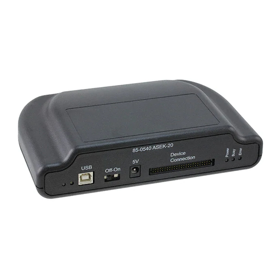
ASEK-20 Kit (Part # 85-0540-600)
o ASEK-20 Chassis with main Motherboard inside (85-0540-004)
o USB Communications Cable
o DC Power Supply/Cable with AC Outlet Adapters
o Proto Board ( Part # 85-0540-103)
o Ribbon Cable (Part # 85-0540-300)
ASEK-1335-SUBKIT-T:
o A1335 Daughterboard (Part #: 85-0540-109 / Stenciled A1332)
o A1335 Socketed single die grand-daughter board (Part #: 85-0723 / Stenciled
ASEK1335-SD)
o A1335 Socketed dual die grand-daughter board (Part #: 85-0716)
Figure 1. ASEK-20-T--KIT
Instructions for Configuring ASEK-1335-T-KIT with Device On-Board
1. Connect one end of the USB communications cable to a personal computer
2. Connect the other end of the USB communications cable to the "USB" port on the ASEK-20 chassis
3. Connect the ribbon cable to the J2 connector on the daughterboard (85-0540-109)
4. Connect the other end of the ribbon cable to the "Device Connection" port on the ASEK-20 chassis
5. Mount the socketed grand-daughterboard (either 85-0723 or 85-716) onto the daughter board (85-
0540-109)
ASEK-1335-T-KIT
ASEK-1335-T-KIT Quick Guide
Figure 2. ASEK-1335-SUBKIT-T
Page 1 of 5
Advertisement
Table of Contents

Related Manuals for Allegro MicroSystems ASEK-1335-T-KIT


Summary of Contents for Allegro MicroSystems ASEK-1335-T-KIT
- Page 1 19 February 2016 ASEK-1335-T-KIT Quick Guide The ASEK-1335-T-KIT as described below is for the purpose of evaluating the A1335 device. ASEK-1335-T-KIT Bill of Materials ASEK-20 Kit (Part # 85-0540-600) o ASEK-20 Chassis with main Motherboard inside (85-0540-004) o USB Communications Cable...
- Page 2 (Single Die) 85-0540-109 Daughterboard Figure 3. Setup of ASEK-1335-T-KIT Configuring ASEK-1335-T-KIT for Off-Board Prototyping The A1335 daughterboard allows off-board connections via a 12-pin header, seen in Figure 4 as component J3. This connector may be used in evaluating external prototyping modules.
- Page 3 If the appropriate COM port driver is not installed automatically, latest versions may be found on the FTDI website below: http://www.ftdichip.com/Drivers/VCP.htm A1335 Sample Devices A1335 samples are not included with the ASEK-1335-T-KIT. Please contact your local FAE or factory for samples. ASEK-1335-T-KIT Page 3 of 5...
- Page 4 Device ISEL ASEK-20 Daughterboard Figure A-1. A1335 Daughterboard J3 Header Wiring Diagram (I C Mode) MODULE PIN 1 SENT SENT Allegro Device ISEL ASEK-20 Daughterboard Figure A-2. A1335 Daughterboard J3 Header Wiring Diagram (Manchester Mode) ASEK-1335-T-KIT Page 4 of 5...
- Page 5 Change Description Res. Page(s) Date Original release 7/31/2014 Removed line not applicable to A1335 8/11/2014 Added link for software portal and text edits 3/30/2015 Added J3 header configuration instructions and 3/11/2016 wiring diagrams; text edits ASEK-1335-T-KIT Page 5 of 5...
Need help?
Do you have a question about the ASEK-1335-T-KIT and is the answer not in the manual?
Questions and answers