Table of Contents
Advertisement
Quick Links
INTRODUCTION
The A89503 demo board is designed to aid system designers with evaluating the operation and performance of Allegro's
A89503 48V Safety Automotive, Half-Bridge MOSFET Driver. This application note describes the components of the
A89503 Demo Board and explains how it can be used to achieve normal operation. To simplify understanding, components
of the demo board are categorized into different topics.
......................................................................... 1
.................................................................... 2
...................................................................... 2
................................................................... 2
........................................................................ 2
........................................................... 2
............................................................................. 2
................................................................................ 3
UM-A89503
MCO-0001172
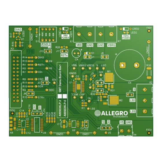
Figure 1: A89503 Demo Board
Table of Contents
.................................................................................. 3
User Manual
A89503 Demo Board
.................................................................. 3
.............................................................................. 3
................................................................... 6
.................... 4
.................... 5
December 9, 2021
Advertisement
Table of Contents

Related Manuals for Allegro MicroSystems A89503


Summary of Contents for Allegro MicroSystems A89503
-
Page 1: Table Of Contents
A89503 Demo Board INTRODUCTION The A89503 demo board is designed to aid system designers with evaluating the operation and performance of Allegro’s A89503 48V Safety Automotive, Half-Bridge MOSFET Driver. This application note describes the components of the A89503 Demo Board and explains how it can be used to achieve normal operation. To simplify understanding, components of the demo board are categorized into different topics. -
Page 2: Power Supplies
The linear regulator U2 is fitted on both the 5 V and 3.3 V boards. tor so when they are left floating, they are pulled to logic low. Although this is a 5 V regulator, the A89503-3 logic inputs are The LSn pin contains an internal pull-up resistor that pulls it to tolerant to this voltage level, will operate correctly, and will not logic high when it is left floating. -
Page 3: Resetn
JUMPERS The A89503 contains a RESETn input pin that allows the device The 10 different jumpers of the A89503 demo board are used as to be put into standby mode when it is pulled low. This pin has a follows: voltage rating up to the supply voltage, so it can be directly con- •... -
Page 4: A89503Klp Smt Demo Board Schematic (1 Of 2)
A89503 DEMO BOARD SCHEMATIC LM2936HV-3.3 1N4148W X4.1 X1.2 VREG X4.2 CRD1 X1.1 E-202 100n 100n LED1 POWER RSTn 6k65 X7.1 470n VBRG 100V 100V CRD2 X7.2 E-202 2.2u 1 2 3 4 VREG LED2 VBRG VREG POWER VREG X3.23 ENABLE... -
Page 5: A89503Klp Smt Demo Board Schematic (2 Of 2)
RSTn T IT L E : A89503KLP SMT Demonstration Board STRn nt = Text to be visible on PCB silkscreen. Figure 3: A89503KLP SMT Demo Board Schematic (2 of 2) Allegro MicroSystems 955 Perimeter Road Manchester, NH 03103-3353 U.S.A. www.allegromicro.com... -
Page 6: Revision History
Copyright 2021, Allegro MicroSystems. Allegro MicroSystems reserves the right to make, from time to time, such departures from the detail specifications as may be required to permit improvements in the performance, reliability, or manufacturability of its products. Before placing an order, the user is cautioned to verify that the information being relied upon is current.
Need help?
Do you have a question about the A89503 and is the answer not in the manual?
Questions and answers