Advertisement
ACS732 AND ACS733 DEMO BOARD AND COMPONENTS
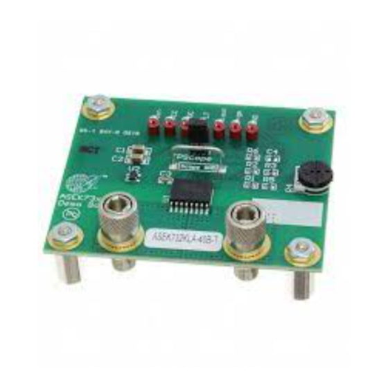
Allegro ACS732/33 demo board is pictured in Figure 1 below. Refer to Table 1 for symbol names and descriptions of onboard
components. Note: Board is pictured without Allegro device.
Table 1: Summary of Demo Board Components
Symbol
U1
U2
Jumper
C1, C2
C3
R4
ASEK732-3-UM
MCO-0000744
ACS732 and ACS733 Evaluation Board
Figure 1: Allegro ACS733 Current Sensor Demo Board
Location of Allegro ACS733 (V
3.3 or 5 V Regulator
Removes regulator and capacitors C1, C2 from V
Regulator output capacitors; removed from the circuit via the jumper
0.1 µF device bypass capacitor; is always connected
Potentiometer to set voltage on V
Description
= 3.3 V) or ACS732 (V
= 5 V)
CC
CC
; C3 (0.1 µF) still present at device
CC
pin; V
voltage sets fault current level
OC
OC
User Manual
December 6, 2019
Advertisement
Table of Contents

Related Manuals for Allegro MicroSystems ACS732


Summary of Contents for Allegro MicroSystems ACS732
- Page 1 ACS732 and ACS733 Evaluation Board ACS732 AND ACS733 DEMO BOARD AND COMPONENTS Allegro ACS732/33 demo board is pictured in Figure 1 below. Refer to Table 1 for symbol names and descriptions of onboard components. Note: Board is pictured without Allegro device.
- Page 2 Figure 2: Schematic for ACS732 and ACS733 Demo Board PINOUT DIAGRAM AND TERMINAL LIST Table 2: Terminal List Table Number Name Description 1,2,3,4 Positive terminals for current being sensed; fused internally. 5,6,7,8 IP– Negative terminals for current being sensed; fused internally.
- Page 3 December 6, 2019 Initial Release Copyright 2019, Allegro MicroSystems. The information contained in this document does not constitute any representation, warranty, assurance, guaranty, or inducement by Allegro to the customer with respect to the subject matter of this document. The information being provided does not guarantee that a process based on this infor- mation will be reliable, or that Allegro has explored all of the possible failure modes.
Need help?
Do you have a question about the ACS732 and is the answer not in the manual?
Questions and answers