Table of Contents
Advertisement
Quick Links
All manuals and user guides at all-guides.com
v.LiNK Video-inserter
VL2-PCM31
Compatible with
PORSCHE vehicles
with PCM 3.1 infotainment
Video-inserter with 2 video inputs and 1 rear-view camera input with CAN control
Product features
Video-inserter for factory-infotainment systems
2 video-inputs for after-market devices (e.g. DVD-Player, DVB-T tuner)
Built-in audio-switch (no audio-insertion)
Rear-view camera video-input
Automatic switching to rear-view camera input on engagement of the reverse gear
Activatable parking guide lines for rear-view camera (not for all vehicles available)
Video-in-motion (ONLY for connected video-sources)
Video-inputs PAL / NTSC compatible
Version 14.06..2018
HW: LVDS
.......VL2-PCM31
Advertisement
Table of Contents

Related Manuals for Car-Interface VL2-PCM31


Summary of Contents for Car-Interface VL2-PCM31
- Page 1 All manuals and user guides at all-guides.com v.LiNK Video-inserter VL2-PCM31 Compatible with PORSCHE vehicles with PCM 3.1 infotainment Video-inserter with 2 video inputs and 1 rear-view camera input with CAN control Product features Video-inserter for factory-infotainment systems 2 video-inputs for after-market devices (e.g. DVD-Player, DVB-T tuner) ...
-
Page 2: Table Of Contents
Picture settings and guide lines 3. Video interface operation 3.1. By infotainment button 3.2. By external keypad or white wire of the 6pin cable 4. Specifications 5. FAQ – Trouble Shooting-Interface functions 6. Technical support Version 14.06..2018 HW: LVDS …….VL2-PCM31... -
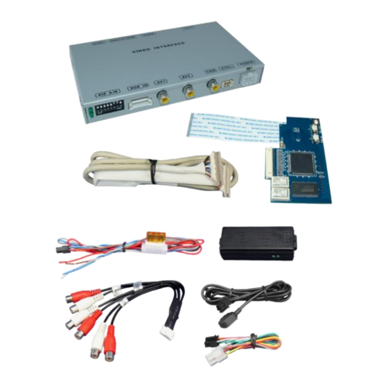
Page 3: Prior To Installation
Read the manual prior to installation. Technical knowledge is necessary for installation. The place of installation must be free of moisture and away from heat sources. 1.1. Delivery contents Take down the serial number of the interface and store this manual for support purposes: ____________________ Version 14.06..2018 HW: LVDS …….VL2-PCM31... -
Page 4: Checking The Compatibility Of Vehicle And Accessories
Factory rear-view camera Automatically switching-back from inserted video to factory rear-view camera is only possible while the reverse gear is engaged. To delay the switch-back an additional electronic part is required. Version 14.06..2018 HW: LVDS …….VL2-PCM31... -
Page 5: Boxes And Connectors
Further it reads the vehicle’s digital signals out of the vehicle’s CAN-bus and converts them for the video interface. 1.3.2. CAN-bus box The CAN box reads the vehicle’s digital signals out of the vehicle’s CAN-bus and converts them for the video interface. Version 14.06..2018 HW: LVDS …….VL2-PCM31... -
Page 6: Dip-Switch Settings - Interface (Black)
If set to ON, the interface switches to its rear-view camera input while the reverse gear is engaged. 1.3.3.3. Monitor selection (dip6, 7-and 8) Set to OFF Note: Dip 1 and 4are out of function and have to be set to OFF. Version 14.06..2018 HW: LVDS …….VL2-PCM31... -
Page 7: Installation
The boxes shall be installed behind the vehicle`s head-unit or the glove department, depending on equipment and space. 2.1.2. Place of installation - daughter PCB The interface’s daughter PCB is prepared to be installed in the head unit’s housing. Version 14.06..2018 HW: LVDS …….VL2-PCM31... -
Page 8: Connection Schema
All manuals and user guides at all-guides.com 2.2. Connection schema Version 14.06..2018 HW: LVDS …….VL2-PCM31... -
Page 9: Opening The Factory Head Unit
Clip out and lever the fixing points of the head unit’s upper and lower housing parts (red arrows) all around the housing and carefully separate both parts. Pay attention to sensitive cable connections between the parts and disconnect before separating! Version 14.06..2018 HW: LVDS …….VL2-PCM31... - Page 10 50pin ribbon cable base of the factory PCB. Make sure that the connector pins are faced in the invisible direction. After a check of its perfect position, close the ribbon cable base’s lock by pushing downwards the white hinge, to fix the connection again. Version 14.06..2018 HW: LVDS …….VL2-PCM31...
- Page 11 Reconnect the original 30pin ribbon cable to the mainboard’s 30pin ribbon cable base. After a check of its perfect position, close the ribbon cable base’s lock by pressing the black hinge, to save the connection again. Version 14.06..2018 HW: LVDS …….VL2-PCM31...
-
Page 12: Warning Notes, Concerning The Installation Of Ribbon Cables
(Pay attention to the cable’s caption “MONITOR SIDE” and “BOX SIDE”) Lead the connected picture signal cable out of the head unit at the location that’s shown in the picture and save it against cable damage. Version 14.06..2018 HW: LVDS …….VL2-PCM31... - Page 13 UP position. Take care for installing the picture signal cable in the right direction, as both connectors seem to be identical. (Pay attention to the cable’s caption “MONITOR SIDE” and “BOX SIDE”) Version 14.06..2018 HW: LVDS …….VL2-PCM31...
-
Page 14: Connecting Video-Interface - Power/Can
Note: Check the LEDs of the CAN box after reconnecting the battery - one must be on, the second one must be flashing. If this is not the case, the interface’s analogue connection is required by using the 6pin cable with open wire ends (see following chapter). Version 14.06..2018 HW: LVDS …….VL2-PCM31... -
Page 15: Connection Video-Interface - Analogue
Note: The connection of the green wire (Reverse signal) will be described in chapter “After- market rear-view camera”. The white wire will be used to switch the enabled video sources (see chapter “video interface – operation”). The grey wire stays unconnected. Version 14.06..2018 HW: LVDS …….VL2-PCM31... -
Page 16: Connection - Video Sources
Note: The picture settings for CAM input have to be adjusted in AV2. Connect the RCA of the video source 1 and video source 2 to the female RCA „Video IN1“ and „Video IN2“ of the video cable. Version 14.06..2018 HW: LVDS …….VL2-PCM31... -
Page 17: Audio-Switch And Audio-Insertion
RCA port “Audio OUT”. Connect the audio-RCA of AV-source 1 and AV source 2 to the female RCA port of the audio cable’s „Audio 1 IN“ und „Audio 2 IN“. Version 14.06..2018 HW: LVDS …….VL2-PCM31... -
Page 18: After-Market Rear-View Camera
„CAMERA IN“ while the reverse gear is engaged. Additionally, the +12V (max. 500mA) power supply for the rear-view camera can be taken from the green wire of the 6pin to 8pin cable. Version 14.06..2018 HW: LVDS …….VL2-PCM31... -
Page 19: Case 2: Can-Box Does Not Receive The Reverse Gear Signal
Connect the rear-view camera power wire and the green wire (video interface side) of the 6pin to 8pin cable both to output terminal (87) of the relay. Connect permanent battery power to input terminal (30) of relay. Version 14.06..2018 HW: LVDS …….VL2-PCM31... -
Page 20: Connecting Video-Interface - External Keypad
Connect the keypad’s female 4pin connector to the male 4pin connector of the video- interface. Note: Even if the switching through several video sources by the keypad mightn’t be required, the keypad’s invisible connection and availability is strongly recommended. Version 14.06..2018 HW: LVDS …….VL2-PCM31... -
Page 21: Picture Settings And Guide Lines
Note: If there is no communication between the CAN box and the vehicle`s CAN-bus (several vehicles aren’t compatible), the reverse gear guide-lines can`t be shown during the vehicle’s operation, even if they once appear after having switched the system to powerless! Version 14.06..2018 HW: LVDS …….VL2-PCM31... -
Page 22: Video Interface Operation
Alternatively or additionally to the factory-infotainment-buttons the interface’s keypad or the white wire of the 6pin cable can be used to switch the enabled inputs. Every +5-12V pulse switches the video interface to the next enabled input. Version 14.06..2018 HW: LVDS …….VL2-PCM31... -
Page 23: Specifications
0.7V with 75 Ohm impedance Temperature range -40°C to +85°C Dimensions video-box 158 x 22 x 93 mm (W x H x D) Dimensions CAN-box 73 x 22 x 30 mm (W x H x D) Version 14.06..2018 HW: LVDS …….VL2-PCM31... -
Page 24: Faq - Trouble Shooting-Interface Functions
Camera input picture fluorescent light which shines Test camera under natural light outside the garage. flickers. directly into the camera. Camera input picture is Protection sticker not Remove protection sticker from lens. bluish. removed from camera lens. Version 14.06..2018 HW: LVDS …….VL2-PCM31... -
Page 25: Technical Support
Please note that direct technical support is only available for products purchased directly from NavLinkz GmbH. For products bought from other sources, contact your vendor for technical support. NavLinkz GmbH distribution/tech dealer-support Eurotec-Ring 39 D-47445 Moers +49 2841 949970 Email mail@navlinkz.de 10R-03 5384 Made in China Version 14.06..2018 HW: LVDS …….VL2-PCM31...
Need help?
Do you have a question about the VL2-PCM31 and is the answer not in the manual?
Questions and answers