Table of Contents
Advertisement
Quick Links
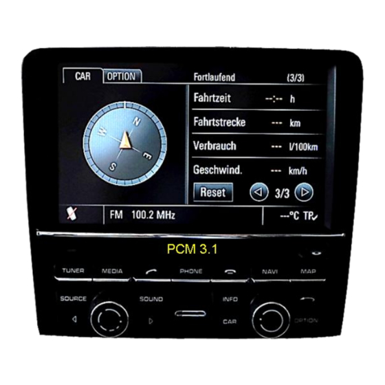
v.LiNK Video-inserter
CI-VL2-PCM31
Compatible with
PORSCHE vehicles
with PCM 3.1 infotainment
Video-inserter with 2 video inputs and 1 rear-view camera input with CAN control
Product features
Video-inserter for factory-infotainment systems
2 video-inputs for after-market devices (e.g. DVD-Player, DVB-T tuner)
Built-in audio-switch (no audio-insertion)
Rear-view camera video-input
Automatic switching to rear-view camera input on engagement of the reverse gear
Activatable parking guide lines for rear-view camera (not for all vehicles available)
Video-in-motion (ONLY for connected video-sources)
Video-inputs PAL / NTSC compatible
Version 14.06..2018
HW: LVDS
CI-VL2-PCM31
Advertisement
Table of Contents

Related Manuals for Car-Interface v.link CI-VL2-PCM31


Summary of Contents for Car-Interface v.link CI-VL2-PCM31
- Page 1 v.LiNK Video-inserter CI-VL2-PCM31 Compatible with PORSCHE vehicles with PCM 3.1 infotainment Video-inserter with 2 video inputs and 1 rear-view camera input with CAN control Product features Video-inserter for factory-infotainment systems 2 video-inputs for after-market devices (e.g. DVD-Player, DVB-T tuner) ...
-
Page 2: Table Of Contents
Contents 1. Prior to installation 1.1. Delivery contents 1.2. Checking the compatibility of vehicle and accessories 1.3. Boxes and connectors 1.3.1. Video-Interface 1.3.2. CAN-bus box 1.3.3. Dip-switch settings – interface (black) 1.3.3.1. Enabling the interface’s video inputs (dip 2-3) 1.3.3.2. Rear-view camera setting (dip 5) 2. -
Page 3: Prior To Installation
Legal Information By law, watching moving pictures while driving is prohibited, the driver must not be distracted. We do not accept any liability for material damage or personal injury resulting, directly or indirectly, from installation or operation of this product. Apart from using this product in an unmoved vehicle, it should only be used to display fixed menus or rear-view- camera video when the vehicle is moving (for example the MP3 menu for DVD upgrades). -
Page 4: Checking The Compatibility Of Vehicle And Accessories
1.2. Checking the compatibility of vehicle and accessories Requirements Brand Compatible vehicles Compatible systems Cayenne E2 Panamera 911 (991) from 09/2011 till 12/2015 Porsche PCM 3.1 Boxster Cayman Macan Limitations: Video only The interface inserts ONLY video signals into the infotainment. For inserting Audio signals either the possibly existing factory audio-AUX-input or a FM- modulator can be used. -
Page 5: Boxes And Connectors
1.3. Boxes and connectors 1.3.1. Video Interface The video-interface converts the video signals of connected after-market sources in a factory monitor compatible picture signal which is inserted in the factory monitor, by using separate trigger options. Further it reads the vehicle’s digital signals out of the vehicle’s CAN-bus and converts them for the video interface. -
Page 6: Dip-Switch Settings - Interface (Black)
1.3.3. Dip-switch settings – interface (black) Some settings have to be selected by the dip-switches on the video interface. Dip position down is ON and position up is OFF. Function ON (down) OFF (up) No function set to OFF CVBS AV1-input enabled disabled CVBS AV2-input... -
Page 7: Installation
2. Installation To install the interface, first switch off the ignition and disconnect the vehicle’s battery. Please read the owner`s manual of the car, regarding the battery`s disconnection! If required, enable the car`s sleep-mode (hibernation mode) In case the sleep-mode does not succeed, the disconnection of the battery can be done with a resistor lead. -
Page 8: Connection Schema
2.2. Connection schema Version 14.06..2018 HW: LVDS CI-VL2-PCM31... -
Page 9: Opening The Factory Head Unit
2.3. Opening the factory head unit Remove the vehicle’s head-unit. Turn out both Torx screws of the head unit’s bottom part of the head unit (red arrows) and both Torx screws at the upper part of the head unit. Clip out and lever the fixing points of the head unit’s upper and lower housing parts (red arrows) all around the housing and carefully separate both parts. - Page 10 2.4. Connection-50pin ribbon cables - Push upwards the white hinges of the factory ribbon cable bases to unlock the original 50pin and 30pin ribbon cables of the factory PCB (red arrows) Carefully pull out both original ribbon cables (yellow arrows). Connect the daughter PCB’s 50pin ribbon cable „...
- Page 11 As shown in the picture, bring the daughter PCB in position and fix it to the mainboard by using the enclosed brass spacer. In case that the daughter PCB’s 50pin ribbon cable had been disconnected before, reconnect it and fix it with the black lock hinge at the ribbon cable base.
-
Page 12: Warning Notes, Concerning The Installation Of Ribbon Cables
2.4.1. Warning notes, concerning the installation of ribbon cables 1) The contacting ends of ribbon cables always have to be installed in a straight and precise 180° position to the connector. Each deviation from a perfect contact position will curse faulty contact and even danger of short circuit 2) The ribbon cable’s contacting side always has to correspond to the contacting side of the connector, concerning the mounting position. - Page 13 2.6. Reconnection of the head unit’s housing parts Clip in the head unit housing’s mounting locations and again fix the parts to the monitor by using the 4 original Torx screws. 2.7. Connection of the picture signal cable Connect the picture signal cable’s female 20pin connector „ BOX SIDE“ to the 20pin connector of the video interface, with its contacting side in the UP position.
-
Page 14: Connecting Video-Interface - Power/Can
2.8. Connecting video-interface – Power / CAN Connect the white female 6pin connector of the 6pin to 8pin cable to the male 6pin connector of the video interface. 1) Solder the red coloured wire of the 4pin Power / CAN cable to Quadlock’s +12V ACC (red) . 2) Solder the brown coloured wire of the 4pin Power /CAN cable to Quadlock’s ground (brown). -
Page 15: Connection Video-Interface - Analogue
2.9. Connecting video-interface – analogue If the communication between the CAN box and the vehicle’s CAN bus does not succeed (not all vehicles are compatible), an analogue connection is required by using the 6pin cable with open wire ends. Connect the female 6pin connector of the 6pin cable to the 6pin connector of the video interface. -
Page 16: Connection - Video Sources
2.10. Connecting Video-sources It is possible to connect two after-market video sources and one after-market rear-view camera to the video-interface. Before final installation of the peripheral devices, we recommend a test-run to detect a incompatibility of vehicle and interface. Due to changes in the production of the vehicle manufacturer there’s always a possibility of incompatibility. -
Page 17: Audio-Switch And Audio-Insertion
2.11. Audio-switch and audio-insertion This interface is only able to insert video signals into the factory infotainment and switch audio signals. If an AV-source is connected to AV1 or AV2, audio insertion must be done by factory audio AUX input or FM-modulator to which the interface’s sound-switch output is connected. -
Page 18: After-Market Rear-View Camera
2.12. After-market rear-view camera Some vehicles have a different reverse gear code on the CAN-bus which the included CAN- box is not compatible with. In this case there are two different ways of installation. If the CAN-box is able to detect an enabled vehicle’s reverse gear, the green wire of the 6pin to 12pin cable carries +12V while the reverse gear is engaged. -
Page 19: Case 2: Can-Box Does Not Receive The Reverse Gear Signal
2.12.2. . Case 2: CAN-box does not receive the reverse gear signal If the CAN-bus interface does not receive +12V on the green wire of the 6pin to 8pin cable when reverse gear is engaged (not all vehicles are compatible) an external switching signal from the reverse gear light is required. -
Page 20: Connecting Video-Interface - External Keypad
2.13. Connecting video-interface - external keypad Connect the keypad’s female 4pin connector to the male 4pin connector of the video- interface. Note: Even if the switching through several video sources by the keypad mightn’t be required, the keypad’s invisible connection and availability is strongly recommended. Version 14.06..2018 HW: LVDS CI-VL2-PCM31... -
Page 21: Picture Settings And Guide Lines
2.14. Picture settings and guide lines The picture settings are adjustable by the 3 push-buttons on the video-interface. Press the MENU button to open the OSD settings menu or to switch to the next menu item. Press UP and DOWN to change the selected value. The buttons are placed inside in the housing to avoid accidental changes during or after the installation. -
Page 22: Video Interface Operation
3. Video interface operation 3.1. By infotainment button To switch the video sources the vehicle’s Call off button or menu button can be used. Each press will switch to the next enabled input. If all inputs are enabled the order is: ... -
Page 23: Specifications
4. Specifications BATT/ACC range 7V - 25V Stand-by power drain 8,6mA Power 160mA Video input 0.7V - 1V Video input formats PAL / NTSC RGB-video amplitude 0.7V with 75 Ohm impedance Temperature range -40°C to +85°C Dimensions video-box 158 x 22 x 93 mm (W x H x D) Dimensions CAN-box 73 x 22 x 30 mm (W x H x D) Version 14.06..2018... -
Page 24: Faq - Trouble Shooting-Interface Functions
FAQ – Trouble shooting Interface functions For any troubles which may occur, check the following table for a solution before requesting support from your vendor. Symptom Reason Possible solution Not all connectors have been reconnected to factory head- Connect missing connectors. unit or monitor after installation. - Page 25 Symptom Reason Possible solution Camera input picture Use relay or electronics to "clean" reverse gear lamp black. Camera power taken directly power. Alternatively, if CAN-bus box is compatible Camera input picture from reverse gear lamp. with the vehicle, camera power can be taken from green wire of 6pin to 8pin cable.
Need help?
Do you have a question about the v.link CI-VL2-PCM31 and is the answer not in the manual?
Questions and answers