Table of Contents
Advertisement
Quick Links
(previous model CI-RL2-MIB2-E)
VW / SEAT / SKODA vehicles
with MIB2 Entry infotainment and 5inch monitor
Video-inserter with 2 video inputs and 1 rear-view camera input
Product features
Video-inserter for factory-infotainment systems
1 CVBS rear-view camera video-input
2 CVBS video-inputs for after-market devices (e.g. USB-Player, DVB-T2 tuner, ...)
Automatic switching to rear-view camera input on engagement of the reverse gear
Video-in-motion (ONLY for connected video-sources)
Video-inputs NTSC compatible
Version 03.02.2023
Video inserter
CI-RL1-MIB2-E
Compatible with
HW: CAM(V31)/(V10)
CI-RL1-MIB2-E
Advertisement
Table of Contents

Related Manuals for Car-Interface CI-RL1-MIB2-E


Summary of Contents for Car-Interface CI-RL1-MIB2-E
- Page 1 Video inserter CI-RL1-MIB2-E (previous model CI-RL2-MIB2-E) Compatible with VW / SEAT / SKODA vehicles with MIB2 Entry infotainment and 5inch monitor Video-inserter with 2 video inputs and 1 rear-view camera input Product features Video-inserter for factory-infotainment systems 1 CVBS rear-view camera video-input ...
-
Page 2: Table Of Contents
2.10. Connection – video sources 2.11. After-market rear-view camera 2.12. Audio insertion 2.13. Connection – video interface and external keypad 2.14. Picture settings 3. Video interface operation 4. Specifications 5. FAQ – Trouble Shooting-Interface function Version 03.02.2023 HW: CAM(V31)/(V10) CI-RL1-MIB2-E... -
Page 3: Prior To Installation
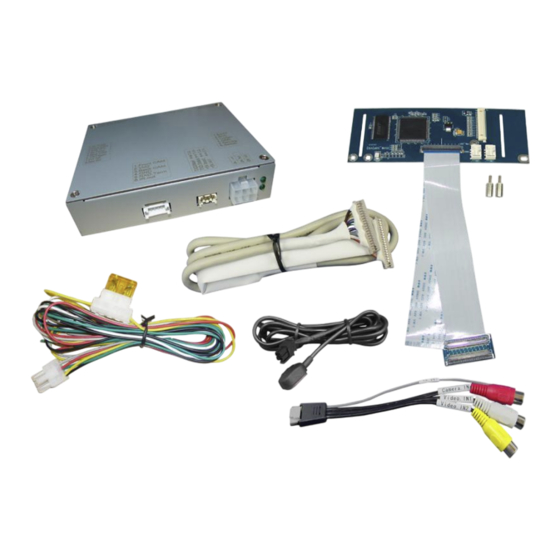
Read the manual prior to installation. Technical knowledge is necessary for installation. The place of installation must be free of moisture and away from heat sources. 1.1. Delivery contents Take down the serial number of the interface and store this manual for support purposes: ____________________ Version 03.02.2023 HW: CAM(V31)/(V10) CI-RL1-MIB2-E... -
Page 4: Checking The Compatibility Of Vehicle And Accessories
Factory rear-view camera Automatically switching-back from inserted video to factory rear-view camera is only possible while the reverse gear is engaged. To delay the switch-back an additional electronic part is required. Video input signal Only NTSC compatible. Version 03.02.2023 HW: CAM(V31)/(V10) CI-RL1-MIB2-E... - Page 5 Further it reads the vehicle’s digital signals out of the vehicle’s CAN-bus and converts them for the video interface. Version 03.02.2023 HW: CAM(V31)/(V10) CI-RL1-MIB2-E...
-
Page 6: Dip-Switch Settings
If set to ON, the interface switches to its rear-view camera input while the reverse gear is engaged. Note: Dips 1, 4, 6, 7 and 8 are out of function and have to be set to OFF. Version 03.02.2023 HW: CAM(V31)/(V10) CI-RL1-MIB2-E... -
Page 7: Installation
The interface is prepared to be connected behind the vehicle`s monitor and head-unit. 2.1.2. Place of installation - daughter PCB The interface’s daughter PCB is prepared to be installed inside or outside the monitor housing depending on the head unit. Version 03.02.2023 HW: CAM(V31)/(V10) CI-RL1-MIB2-E... -
Page 8: Connection Schema
2.2. Connection schema Version 03.02.2023 HW: CAM(V31)/(V10) CI-RL1-MIB2-E... -
Page 9: Connecting Video-Interface - Power
The white wire will be used to switch the enabled video sources (see chapter “video interface – operation”). The possibly existing grey wire is out of function and has to be isolated. Version 03.02.2023 HW: CAM(V31)/(V10) CI-RL1-MIB2-E... -
Page 10: Opening The Factory Monitor (Not Skoda Vehicles)
Turn out the 7 screws (red arrows) at the rear side of the monitor and remove the metal sheet to set free the mainboard’s ribbon cable base with the factory picture signal cable. Version 03.02.2023 HW: CAM(V31)/(V10) CI-RL1-MIB2-E... -
Page 11: Connection Of The 50Pin Ribbon Cables
50pin ribbon cable base of the factory PCB. Make sure that the connector pins are faced to the platinum. After a check of its perfect position, close the ribbon cable base’s lock by folding downwards the black hinge, to fix the connection again. Version 03.02.2023 HW: CAM(V31)/(V10) CI-RL1-MIB2-E... - Page 12 To avoid any kind of vibration-caused short circuits After the connection, it’s necessary to isolate both sides of the merger with some kind of smooth issue tape as shown in the picture beside. Version 03.02.2023 HW: CAM(V31)/(V10) CI-RL1-MIB2-E...
-
Page 13: Warning Notes, Concerning The Installation Of Ribbon Cables
Use a smooth, but thin issue tape because there will be lack of space between the head unit’s and the monitor’s housing. Fix the monitor’s rear metal sheet by using the 7 screws. Version 03.02.2023 HW: CAM(V31)/(V10) CI-RL1-MIB2-E... -
Page 14: Assembly - Head Unit, Monitor And Daughter Pcb
Change the original brass screws against the enclosed brass spacers at the position that’s shown in the picture. Fix the daughter PCB to the brass spacers in the head unit by using the original screws. Version 03.02.2023 HW: CAM(V31)/(V10) CI-RL1-MIB2-E... -
Page 15: Connection - Picture Signal Cable
Due to the limited space inside the monitor housing, a shortening of the PCB is further required (see the following procedures). Version 03.02.2023 HW: CAM(V31)/(V10) CI-RL1-MIB2-E... -
Page 16: Skoda Monitor - Removal And Opening
Turn out the 8 screws (red arrows) at the rear-side of the monitor and remove the metal sheet to set free the mainboard’s ribbon cable base with the factory picture signal cable. Version 03.02.2023 HW: CAM(V31)/(V10) CI-RL1-MIB2-E... -
Page 17: Skoda Monitor Mainboard - Disconnection And Removal
Note: The original short ribbon cable is made by very stiff material. To avoid any breakage it mustn’t be folded back to much, either while the installation nor with the final assembly. Disconnect the female 12pin connector from its 12pin SD card connector (keep connected at mainboard). Version 03.02.2023 HW: CAM(V31)/(V10) CI-RL1-MIB2-E... -
Page 18: Connection Of The 50Pin Ribbon Cables - Skoda
Turn out the 4 screws and remove the monitor panel’s metal frame. 2.9.3. Connection of the 50pin ribbon cables – Skoda vehicles Carefully, sever the 4 predetermined breaking points of the daughter PCB and remove both side parts. Version 03.02.2023 HW: CAM(V31)/(V10) CI-RL1-MIB2-E... - Page 19 PCB, facing with its rear-side to the monitor panel. After leading through the 50pin ribbon cable „CAR-IN“ and the picture signal cable, install the daughter PCB in the inner recess of the metal frame and fix the frame by using the 4 screws. Version 03.02.2023 HW: CAM(V31)/(V10) CI-RL1-MIB2-E...
- Page 20 Reconnect the female 12pin connector to its 12pin SD card connector. Note: Take special care for none-contacting of the PCB’s electronical components to any other metal parts in the housing (isolate, where required!). Version 03.02.2023 HW: CAM(V31)/(V10) CI-RL1-MIB2-E...
-
Page 21: Reassembling - Skoda Head Unit And Monitor
2.9.4. Reassembling – Skoda monitor and head unit Lead the picture signal cable out at an appropriate location and reassemble the monitor’s rear housing part by using the 8 screws. Note: For the cable entry, a housing modification could possibly be required. Version 03.02.2023 HW: CAM(V31)/(V10) CI-RL1-MIB2-E... - Page 22 12pin connector. Screw in both screws at the upside and both screws at the bottom of the head unit. Version 03.02.2023 HW: CAM(V31)/(V10) CI-RL1-MIB2-E...
-
Page 23: Connection - Video Sources
Connect the rear-view camera’s RCA to the female RCA „Camera IN“ of the video cable. Connect the RCA of the video source 1 and video source 2 to the female RCA „Video IN1“ „Video IN2“ of the video cable. Version 03.02.2023 HW: CAM(V31)/(V10) CI-RL1-MIB2-E... -
Page 24: After-Market Rear-View Camera
Connect the output connector (87) of the relay to the rear-view camera’s power- cable, like you did it to the green switching input cable before. Connect stabile and permanent +12V to the relay’s input connector (30). Version 03.02.2023 HW: CAM(V31)/(V10) CI-RL1-MIB2-E... -
Page 25: Audio Insertion
Connect the 4pin female connector of the external keypad to the male 4pin connector of the video interface. Note: Regardless if it’ll be used or not, the external keypad should always be connected! In case of non-using, it should be invisibly hidden together with the video interface. Version 03.02.2023 HW: CAM(V31)/(V10) CI-RL1-MIB2-E... -
Page 26: Picture Settings
Position V = vertical picture position IR-AV1/2 = no function Guide L/R = no function UI-CNTRL (no function) = no function H-SIZE = horizontal picture position rear-view camera V-SIZE = vertical picture position rear-view camera Version 03.02.2023 HW: CAM(V31)/(V10) CI-RL1-MIB2-E... -
Page 27: Video Interface Operation
210mA Video input 0.7V - 1V Video input formats NTSC RGB-video amplitude 0.7V with 75 Ohm impedance Temperature range -40°C to +85°C Dimensions video-box 114 x 25 x 98 mm (W x H x D) Version 03.02.2023 HW: CAM(V31)/(V10) CI-RL1-MIB2-E... -
Page 28: Faq - Trouble Shooting-Interface Function
Camera input picture fluorescent light which shines Test camera under natural light outside the garage. flickers. directly into the camera. Camera input picture is Protection sticker not Remove protection sticker from lens. bluish. removed from camera lens. Version 03.02.2023 HW: CAM(V31)/(V10) CI-RL1-MIB2-E... - Page 29 Cut the grey wire of 6pin to 8pin and isolate both Interface switches compatibility to vehicle is ends. If problem still occurs, additionally cut the white video-sources by itself. limited. wire of 6pin to 8pin cable and isolate both ends. 10R-03 5384 Made in China Version 03.02.2023 HW: CAM(V31)/(V10) CI-RL1-MIB2-E...
Need help?
Do you have a question about the CI-RL1-MIB2-E and is the answer not in the manual?
Questions and answers