Table of Contents
Advertisement
Quick Links
for Mercedes Benz vehicles
with Comand Online NTG5/NTG5.1
Audio20 CD NTG5/NTG5.1
Audio20 USB NTG5/NTG5.1
with 4pin HSD LVDS connector on the monitor
Video-inserter with 2 video + RGB + rear-view camera input and CAN control
Product features
Video-inserter for factory infotainment monitors
2 video-inputs for after-market devices (e.g. DVD-Player, DVB-T tuner, ...)
Built-in audio-switch (no audio-insertion)
Rear-view camera video-input
Automatic switching to rear-view camera input on engagement of reverse gear
Activatable parking guide lines for rear-view camera
RGB-input for after-market navigation
Video-in-motion (ONLY for connected video-sources)
Compatible with factory rear-view camera
AV-inputs PAL/NTSC compatible
Version 15.01.2016
v.LiNK Video-inserter
CI-VL2-MBN51
Advertisement
Table of Contents

Related Manuals for Car-Interface CI-VL2-MBN51


Summary of Contents for Car-Interface CI-VL2-MBN51
- Page 1 Video-inserter CI-VL2-MBN51 for Mercedes Benz vehicles with Comand Online NTG5/NTG5.1 Audio20 CD NTG5/NTG5.1 Audio20 USB NTG5/NTG5.1 with 4pin HSD LVDS connector on the monitor Video-inserter with 2 video + RGB + rear-view camera input and CAN control Product features ...
-
Page 2: Table Of Contents
Case 2: CAN-box does not detect reverse gear 2.6.4.3. Video signal connection 2.7. Connecting video-interface and keypad 2.8. Picture settings and guide lines 3. Interface operation 3.1. By Comand-buttons 3.2. By keypad 4. Specifications 5. Frequently asked questions Version 15.01.2016 CI-VL2-MBN51... -
Page 3: Prior To Installation
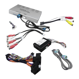
Technical knowledge is necessary for installation. The place of installation must be free of moisture and away from heat sources. 1.1. Delivery contents Take down the serial number of the interface and store this manual for support purposes: ____________________ Version 15.01.2016 CI-VL2-MBN51... -
Page 4: Checking The Compatibility Of Vehicle And Accessories
1.3. Boxes and connectors 1.3.1. Video-interface The video-interface converts the connected after-market sources video signals to an LVDS signal which is the inserted into the factory monitor on certain trigger options. Version 15.01.2016 CI-VL2-MBN51... -
Page 5: Can-Bus Box
1.4.2. RGB-video input signal selection for after-market navigation (Dip 4) If an after-market RGB navigation or other RGB video source is connected, the source’s RGB output signal must match the interface’s RGB video input setting. Version 15.01.2016 CI-VL2-MBN51... -
Page 6: Rear-View Camera Setting (Dip 5)
If power source is not taken directly from the battery, the connection has to be checked for being start-up proven and permanent. 2.1. Place of installation The interface is installed on the backside of the head-unit. Version 15.01.2016 CI-VL2-MBN51... -
Page 7: Connection Schema
2.2. Connection schema Version 15.01.2016 CI-VL2-MBN51... -
Page 8: Connecting Video-Interface And Can-Box
Note: The CAN-box is not compatible with all vehicles. If the CAN-box does not deliver ACC to pin2 of the video-interface or blocks the vehicle CAN, it is possible to install without CAN- box. In this case see also note in chapter after-market rear-view camera if one is supposed to be connected. Version 15.01.2016 CI-VL2-MBN51... -
Page 9: Connection To The Head-Unit - Lvds
Remove blue female 4pin HSD LVDS connector from the rear of the head-unit and connect it to the male 4pin HSD LVDS connector of the interface-box. Connect female 4pin connector of the 4pin HSD LVDS cable to the male 4pin HSD LVDS connector of the head-unit. Version 15.01.2016 CI-VL2-MBN51... -
Page 10: Connection To The Head-Unit - Quadlock
AV-sources and an after-market rear-view camera to the video-interface. Before final installation of the peripheral devices, we recommend a test-run of the interface. Due to changes in the production of the vehicle manufacturer is always the possibility of incompatibility. Version 15.01.2016 CI-VL2-MBN51... -
Page 11: After-Market Rgb Navigation
Connect female 8pin connector of the RGB cable to the male 8pin connector of the video-interface. The loose grey wires have no function and have to be isolated. Connect male 6pin connector of the RGB cable to the after-Market navigation. Version 15.01.2016 CI-VL2-MBN51... -
Page 12: Video-Sources To Av1 And Av2
Connect video RCA of the AV-source 1 to the female RCA connector Video 1 of the video cable. Connect video RCA of the AV-source 2 to the female RCA connector Video 2 of the video cable. Version 15.01.2016 CI-VL2-MBN51... -
Page 13: Audio-Switch And Audio-Insertion
AV-Out of the audio cable. Connect the audio-RCA of the AV-source 1 to the female RCA port AV1 of the audio cable. Connect the audio-RCA of the AV-source 2 to the female RCA port AV2 of the audio cable. Version 15.01.2016 CI-VL2-MBN51... -
Page 14: After-Market Rear-View Camera
6pin to 8pin cable. Connect red-green drilled cable of 6pin of 8pin cable to the male 4pin connector of the video-interface (CAN data exchange, e.g. for steering wheel position for driving path lines) Version 15.01.2016 CI-VL2-MBN51... -
Page 15: Case 2: Can-Box Does Not Detect Reverse Gear
Connect reverse gear light signal/power to coil (85) and ground to coil (86) of relais. Connect rear-view camera power and green wire (video-interface side) of 6pin to 8pin cable to output (87) of relay. Connect permanent battery power to input (30) of relay. Version 15.01.2016 CI-VL2-MBN51... -
Page 16: Video Signal Connection
CAM. Note: Picture settings for CAM input must be done in AV2. 2.7. Connecting video-interface and keypad Connect the female 4pin Microfit connector of the keypad to the male 4pin Microfit connector of the video-interface. Version 15.01.2016 CI-VL2-MBN51... -
Page 17: Picture Settings And Guide Lines
Position H (horizontal) Position V (vertical) Guide lines (ON/OFF) Note: If the CAN-box does not support the very vehicle, the guide-lines cannot be used. If supported and activated, the guide-line also show the steering wheel position dependant driving path. Version 15.01.2016 CI-VL2-MBN51... -
Page 18: Interface Operation
0.3A @12V Power consumption 4.8W Video input formats PAL/NTSC RGB-video amplitude 0.7V with 75 Ohm impedance Temperature range -40°C to +85°C Weight 386g Dimensions (box only) B x H x T 152 x 90 x 210 mm Version 15.01.2016 CI-VL2-MBN51... -
Page 19: Frequently Asked Questions
Camera is being tested under Camera input picture fluorescent light which shines Test camera under natural light outside the garage. flickers. directly into the camera. Camera input picture is Protection sticker not Remove protection sticker. bluish. removed from camera lens. Version 15.01.2016 CI-VL2-MBN51... - Page 20 Cut the grey wire of 6pin to 8pin and isolate both Interface switches compatibility to vehicle is ends. If problem still occurs, additionally cut the white video-sources by itself. limited. wire of 6pin to 8pin cable and isolate both ends. 10R-03 5384 Made in China Version 15.01.2016 CI-VL2-MBN51...
Need help?
Do you have a question about the CI-VL2-MBN51 and is the answer not in the manual?
Questions and answers