iDataLink maestro Rr Install Manual
Hide thumbs
Also See for maestro Rr:
- Install manual (1403 pages) ,
- How to use manual (201 pages) ,
- Manual (106 pages)
Advertisement
SELECT VEHICLE
PRINT PAGES NEEDED
HOW TO USE THIS INSTALL GUIDE
1
Open the Bookmarks menu and find your vehicle OR scroll
down until you find the install guide for your vehicle.
2
Print only the pages for your vehicle using the advanced
options in the Print menu.
3
Install your Maestro RR according to the guide for your vehicle.
Pressing the printer icon or "quick printing" this document will print
NOTICE: Automotive Data Solutions Inc. (ADS) recommends having this installation performed by a certifi ed technician. Logos and trademarks used here in
are the properties of their respective owners.
WARNING
all of the guides in this compilation.
Advertisement
Table of Contents

Related Manuals for iDataLink maestro Rr


Summary of Contents for iDataLink maestro Rr
- Page 1 Print only the pages for your vehicle using the advanced options in the Print menu. Install your Maestro RR according to the guide for your vehicle. WARNING Pressing the printer icon or “quick printing” this document will print all of the guides in this compilation.
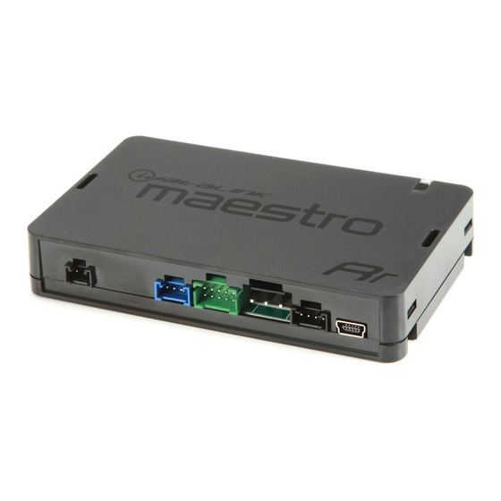
- Page 2 INSTALL GUIDE 2012-2015 Fiat 500 RETAINS STEERING WHEEL CONTROLS, FACTORY AMPLIFIER AND MORE! PRODUCTS REQUIRED OPTIONAL ACCESSORIES iDatalink Maestro RR or RR2 Radio Replacement Interface iDatalink Maestro FI1Installation Harness PROGRAMMED FIRMWARE ADS-RR(SR)-CHR03E-AS ADDITIONAL RESOURCES Maestro RR2 Programmable Outputs Guide NOTICE: Automotive Data Solutions Inc. (ADS) recommends having this installation performed by a certified technician. Logos and trademarks used here...
- Page 3 Fiat 500 2012-2015 WELCOME TABLE OF CONTENTS Installation Instructions Congratulations on the purchase of your iDatalink Maestro RR Radio replacement solution. You are Wiring Diagram without an Amplifi er now a few simple steps away from enjoying your new car radio with Wiring Diagram with an Amplifi...
- Page 4 • Plug the Steering Wheel Control Cable into the aftermarket radio. • Insert the RCA connectors into the aftermarket radio. STEP 5 • Connect all the harnesses to the Maestro RR module then test your installation. Automotive Data Solutions Inc. © 2019 ADS-RR(SR)-FI1-AS-IG-EN...
- Page 5 BLUE AND ME MODULE, UNDER GLOVE BOX CONTROL CABLE UNPLUG BLUE AND ME MODULE WIRES FROM STEP 3 VEHICLE FACTORY RADIO HARNESS STEP 5 MAESTRO RR MODULE N.C. FI1 T-HARNESS NOT REQUIRED DATA CABLE AUDIO CABLE Automotive Data Solutions Inc. © 2019 ADS-RR(SR)-FI1-AS-IG-EN maestro.idatalink.com...
- Page 6 BLUE AND ME MODULE, UNDER GLOVE BOX UNPLUG BLUE AND ME MODULE STEERING WHEEL CONTROL CABLE STEP 3 FACTORY RADIO HARNESS WIRES FROM VEHICLE STEP 5 N.C. MAESTRO RR MODULE FI1 T-HARNESS NOT REQUIRED DATA CABLE AUDIO CABLE Automotive Data Solutions Inc. © 2019 ADS-RR(SR)-FI1-AS-IG-EN maestro.idatalink.com...
- Page 7 Reverse Light Purple/White Orange/White Purple/White Purple/White Purple/White E-Brake Lt Green Yellow/Blue Lt Green Lt Green Lt Green Foot Brake Yellow/Black Yellow/Black N⁄A N⁄A VSS (vehicle speed sensor) (DATA) Pink Green/White Pink Pink Automotive Data Solutions Inc. © 2019 ADS-RR(SR)-FI1-AS-IG-EN maestro.idatalink.com...
- Page 8 There is no fi rmware on the module; fl ash the RR module. RED ONCE MAESTRO RR RESET PROCEDURE: Turn the key to the OFF position, then disconnect all connectors from the module. Press and hold the module’s programming button and connect all the connectors back to the module. Wait, the module’s LED will fl ash RED rapidly (this may take up to 10 seconds).
Need help?
Do you have a question about the maestro Rr and is the answer not in the manual?
Questions and answers