Advertisement
Quick Links
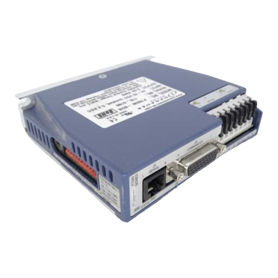
P70530 (DC) High Performance Micro-stepping Drive
Quick Start Guide
Part # M-SD-7DC-07
Initial Release
NOTE: This is only a Quick Start Guide. Visit our website at
http://www.kollmorgen.com/documents/ or browse the Product
Support Package CD-ROM shipped with your product to find the
complete Installation Reference.
Keep all product manuals as a
product component during the life
span of the stepper drive.
Pass all product manuals to future
users/owners of the stepper drive.
Advertisement

Related Manuals for Kollmorgen P70530


Summary of Contents for Kollmorgen P70530
- Page 1 P70530 (DC) High Performance Micro-stepping Drive Quick Start Guide Part # M-SD-7DC-07 Initial Release NOTE: This is only a Quick Start Guide. Visit our website at http://www.kollmorgen.com/documents/ or browse the Product Support Package CD-ROM shipped with your product to find the complete Installation Reference.
- Page 2 Printed in the United States of America Notice Not for use or disclosure outside of Kollmorgen except under written agreement. All rights are reserved. No part of this book shall be reproduced, stored in retrieval form, or transmitted by any means, electronic, mechanical, photocopying, recording, or otherwise without the written permission from the publisher.
- Page 3 P7000 SERIES Cable Part Number: P7S2-232-9D Typical Stepper Wire Color Code A- Orange A+ Black B- Yellow B+ Red PE Green/Yellow Stripe MOTOR EARTH GND Positive Power Supply Terminal 20 VDC - 75 VDC Negative Power Supply Terminal EARTH GND l a i Release...
- Page 4 Install P7000Tools Install P7000Tools either from the Product Support Package CD-ROM or download it from the website (www.kollmorgen.com). When you install P7000Tools, the Installation Wizard will check to see if you have a previous version of P7000Tools on your system. If found, it will uninstall it.
- Page 5 Go to the Advanced Setup screen. Enable the "Anti-Resonance" function. M-SD-7DC-07 Initial Release...
- Page 6 Jog the motor Positive. If successful, your system is now ready for programming for your application. Refer to the Installation Reference found on the Product Support Package CD-ROM or download it from the website (www.kollmorgen.com). l a i Release M-SD-7DC-07...
-
Page 7: Status Display
Status Display There are 7 faults that may occur with the P7000 drive. The fault output latches when they occur. Determine the type of fault by viewing the front panel or through the serial port. The front panel LED turns red and blinks according to the table below. - Page 8 LED Color Blinks Description Cause Solution Solid FLASH A FLASH Without memory memory attempting to fault checksum connect to the validation has drive, failed download the indicating most current corruption of firmware file the operating from the system. P7000Tools menu option This typically Drive->Update occurs during...
- Page 9 LED Color Blinks Description Cause Solution Stall Fault Reduce move Encoderless profile Stall acceleration, Detection velocity, feature has deceleration or detected that load inertia. the motor has Power cycle or slipped or reset drive via stalled. Fault Reset input or P7000Tools.
- Page 10 LED Color Blinks Description Cause Solution Over-voltage Reduce Fault regenerative deceleration, event has load inertia, or occurred reduce which forced deceleration the bus duty cycle to voltage above allow enough 440 VDC. time for the power dump Incoming AC circuit to line voltage recover.
- Page 11 LED Color Blinks Description Cause Solution System Fault An error Power cycle or occurred reset drive via while Fault Reset attempting to input or converge on a P7000Tools. solution while running the Motor Probe or Auto X- Smoothness Probe. Under- Attempting to Power cycle or voltage Fault...
- Page 12 LED Color Blinks Description Cause Solution EEPROM User non- Restore default Checksum volatile configuration Fault memory from the checksum P7000Tools validation has menu option failed Drive->Restore indicating Default user setup Configuration corruption. … Open Phase A motor Check Fault phase is open continuity of motor cable and motor...
- Page 13 The blinking continues until the drive is reset by one of the following methods: Power Cycle GUI Control Fault Reset (Configurable General Purpose Input) M-SD-7DC-07 Initial Release...
- Page 14 NOTES Initial Release M-SD-7DC-07...
-
Page 16: Sales And Service
Sales and Service Kollmorgen is committed to quality customer service. Our products are available world-wide through an extensive authorized distributor network. To serve in the most effective way, please contact your local sales representative for assistance. If you are unaware of your local sales representative, please contact us.
Need help?
Do you have a question about the P70530 and is the answer not in the manual?
Questions and answers