Table of Contents
Advertisement
Quick Links
Install Guide CT32
Caution
• Your thermostat is a precise instrument, handle it with care.
• Turn off electricity to the HVAC system before installing or
servicing thermostat or any part of the system.
• Do not turn electricity back on until work is completed.
• Do not short (jumper) across electric terminals at the control
on the furnace or air conditioner to test the system. This may
damage the thermostat.
• All wiring must conform to local codes and ordinances.
• This thermostat is designed for use with 24 volt AC HVAC
and millivolt gas systems. The thermostat is powered by 4AA
alkaline batteries and/or 24 volt AC C wire (or a 12-24 AC or
DC source). Each thermostat relay load should be limited to 1.0
amp; higher amperage may cause damage to the thermostat.
Caution
to prevent damage to the furnace, air conditioner, and
disconnect the power supply
thermostat,
beginning work. This can be done at the circuit breaker.
1202-003-006
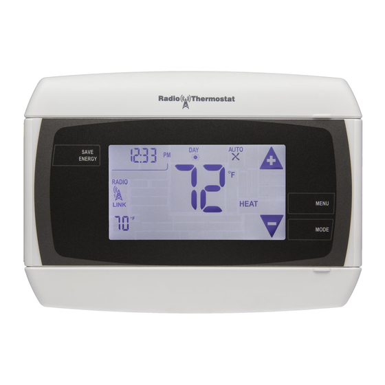
INSTALLATION
To avoid electrical shock and
before
top cover
Reset
HVAC
selections
switches
Save
Energy
button
Power Grid
status
indicator
bottom
cover
Wire
terminal
MENU
button
Mode
button
Touch screen
ENGLISH
Advertisement
Table of Contents

Related Manuals for Radio Thermostat CT32


Summary of Contents for Radio Thermostat CT32
- Page 1 Install Guide CT32 Caution top cover Reset • Your thermostat is a precise instrument, handle it with care. • Turn off electricity to the HVAC system before installing or HVAC selections servicing thermostat or any part of the system. switches •...
- Page 2 A new location will require moving your wiring. For new installations and relocating the CT32 - follow the guidelines listed below: • Locate the thermostat on an inside wall, about 5 ft. (1.5m) above the floor, and in a room that is used often.
- Page 3 REMOVE OLD UNIT Switch OFF electricity to the HEATING and COOLING systems. Then follow these steps: • Remove cover from old thermostat. Most are snap-on types and simply pull off. Some have locking screws on the side or front. These must be loosened. DO NOT remove wires. Note the letters printed near the terminals.
-
Page 4: What Wires Do You Have
Please follow these guidelines for safe and secure wire connections: • You will need at least 2.6” of wire for each of your connections to the CT32. • If you do not have enough wire, splice additional wire to allow enough slack. - Page 5 Find the step-by-step diagram for your system C W R C W R G C W Y R G C W Y RH RC G • Select the reference page F r o m 3 Wire with your wiring diagram and F r o m F r o m F r o m...
-
Page 6: Connect Your Wires
C wire is above the C System terminal, the W above the W. This allows the CT32 to fit snug to the wall. 2.6" • Position the Wires behind the CT32 and up over the terminal area. - Page 7 Mount the CT32 to Wall 1. Hold the CT32 against the wall, with the wires coming over the top; Wall above terminal block. The CT32 will cover the hole in the wall. 2. Position CT32 for best appearance. Place wires inside cover CT32 3.
-
Page 8: Hvac Selection
• With all the wires connected it is time to turn the AC power back on. Do this at the breaker you used to switch it off. The CT32 will power-up in the OFF mode. Your CT32 is not configured to operate your HVAC system yet. You must now configure your thermostat for your HVAC... - Page 9 Caution Special Thermostat Battery Cautions Always replace the batteries as soon as the “Low Batt” flashes. The thermostat is a battery powered device. You must be responsible to replace batteries before they run out. Failure to replace batteries can result in overheating or excessive cooling of your house.
- Page 10 2 stage HEAT, 2 stage COOL select 2 stage HEAT PUMP with 2 stage AUX heat select F IMPORTANT: You must touch HOME after you have made you configuration selection. This will save this configuration into permanent memory of the CT32.
-
Page 11: Test Installation
Test Installation Follow these procedures to verify you have correctly AUTO installed the CT32. TO CHECK FAN (If you connected the G wire): RADIO Touch the fan icon on the HOME screen to turn the fan ON. Verify that air is blowing from the system. - Page 12 4 minute off-time protects the compressor from damage. This thermostat runs on 4AA batteries. The CT32 can be externally powered with a power source rated from 12V to 24V, AC or DC, at 100ma or greater. If used, connect to the C and RH terminals (no polarity). The 24VAC “C”...
- Page 13 STEP 2 - Connect the W wire to the W terminal. THERMOSTAT This connects the heat. STEP 3 - Connect the C wire to the C terminal. Your heater is now connected to the CT32. Please Go To Page 6 4 Wire Heat HVAC SYSTEM STEP 1 - Connect the R (or RH) wire to the RH terminal.
- Page 14 STEP 4 - Connect the G wire to the G terminal on the thermostat. POWER This connects the fan. STEP 5 - Connect the C wire to the C terminal. Your HVAC system is now connected to the CT32. C B O W W RC G A Please Go To Page 6...
- Page 15 RH G Multi-stage Heat and Multi-stage Cool POWER The CT32 can handle up to 2 stages of HEAT and 2 stages of COOL. STEP 1 - Connect the W, W2 wires to the W terminals. This connects the stages of HEAT.
- Page 16 Multi-stage Heat Pump with Multi-stage Aux Heat The CT32 can handle up to 2 stages of Pump compression and 2 stages of AUX heat. STEP 1 - Connect O wire to the O terminal or B wire to the B. This connects the change-over valve.
-
Page 17: Wire Reference Table
Wire Reference Table Possible Wires What They Control R or V or VR RH and RC Single power for HEAT and COOL RH or 4 RH Power for HEAT (RH not connected to RC jumper removed) RC Power for COOL (RH not connected to RC jumper removed) W / AUX W Heat control or heat pump auxiliary heat W2 / AUX2... - Page 18 Possible Wires What They Control based on diagrams below to the correct terminal on the Lennox Heat Pump CT32. The third wire on your valve may be called 6, Y, V or VR or R RH Power for HEAT or G.
Need help?
Do you have a question about the CT32 and is the answer not in the manual?
Questions and answers