Advertisement
Install Guide CT50
Caution
• Your thermostat is a precise instrument, handle it with care.
• Turn off electricity to the HVAC system before installing or
servicing thermostat or any part of the system.
• Do not turn electricity back on until work is completed.
• Do not short (jumper) across electric terminals at the control
on the furnace or air conditioner to test the system. This may
damage the thermostat.
• All wiring must conform to local codes and ordinances.
• This thermostat is designed for use with 24 volt AC and
millivolt systems (with a separate 24VAC power adapter).
• This thermostat requires 24VAC power at the "C" terminal.
• Each thermostat relay load should be limited to 1.0 amp;
higher amperage may cause damage to the thermostat.
Caution
and to prevent damage to the furnace, air conditioner, and
disconnect the power supply
thermostat,
beginning work. This can be done at the circuit breaker.
1014-001-001
To avoid electrical shock
before
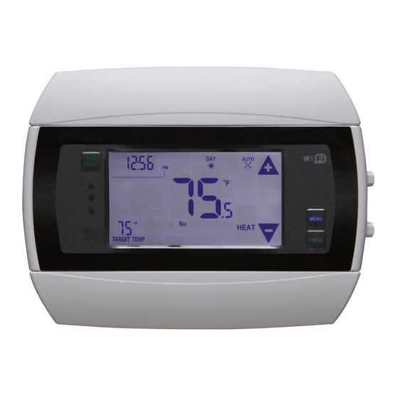
top cover
Reset
button
HVAC
selection
switches
Save
Energy
button
RAD IO
Insulation
indicator
1
LINK
TAR GET TEM P
bottom
cover
DAY
AUT O
PM
F
CO OL
Touch screen
ENGLISH
1
PG
Wire
terminals
Mode
button
Fan
button
MENU
butto
n
PROG
butto
n
Advertisement
Table of Contents

Related Manuals for Radio Thermostat CT50


Summary of Contents for Radio Thermostat CT50
- Page 1 Install Guide CT50 Caution • Your thermostat is a precise instrument, handle it with care. top cover • Turn off electricity to the HVAC system before installing or Reset button servicing thermostat or any part of the system. HVAC • Do not turn electricity back on until work is completed.
- Page 2 A new location will require moving your wiring. For new installations and relocating the CT50 - follow the guidelines listed below: • Locate the thermostat on an inside wall, about 5 ft. (1.5m) above the floor, and in a room that is used often.
-
Page 3: Remove Old Unit
REMOVE OLD UNIT Switch OFF electricity to the HEATING and COOLING systems. Then follow these steps: • Remove cover from old thermostat. Most are snap-on types and simply pull off. Some have locking screws on the side or front. These must be loosened. DO NOT remove wires. Note the letters printed near the terminals. -
Page 4: What Wires Do You Have
HVAC system makers. IMPORTANT: The CT50 runs on 3 AA alkaline batteries and/or the C wire if available. If you do not have a C wire you can run a new wire from the HVAC or use a standard 18-24V [AC or DC] wall transformer. - Page 5 Find the step-by-step diagram for your system • Select the referenece C W RH Go To Page 13 page with your wiring F r o m from 2 Wire F u r n a c e HVAC Heat diagram and set-up C W RH G C W Y RH G C W Y RH RC G...
-
Page 6: Connect Your Wires
NOTE: If you wish you can mount the CT50 to the wall first, and then connect the wires. • The CT50 can be externally powered with a power source rated from 18V to 24V, AC or DC, at 100ma or greater. If used, connect to the C and RH terminals (no polarity). - Page 7 3. Attach the CT50 to the wall with the screws provided. CT50 4. If you are mounting the CT50 to sheet rock or if you are using the old mounting holes, use the plastic anchors provided. 5. Mark first and drill a 3/16-in.(4.8mm) hole for the insert at each screw location, then mount the unit.
-
Page 8: Hvac Selection
• With all the wires connected it is time to turn the AC power back on. Do this at the breaker you used to switch it off. The CT50 will power-up in the OFF mode. Your CT50 is not configured to operate your... - Page 9 Caution Special Battery Warning Always replace the batteries as soon as the “Low Batt” flashes. The thermostat requires batteries for mempry back-up. You must be responsible to replace batteries before they run out. Failure to replace batteries can result in overheating or excessive cooling of your house. •...
-
Page 10: Heat And Cool
NOTE: For 2 stage systems your CT50 can recover from a temperature setback in 2 ways: 1] Fast Recovery - This uses your 2nd stage to bring the house to Target Temperature. This may use slightly more energy. 2] Efficient Recovery -This uses the 2nd stage to bring your house to within a few degrees of the Target Temperature and then uses the 1st stage to go the last bit. -
Page 11: Test Installation
Test Installation Follow these procedures to verify you have correctly installed the CT50. TO CHECK FAN (If you connected the G wire): Press the fan button to turn the fan ON. Verify that air is blowing from the system. Press the fan button again to return to AUTO. - Page 12 +/- buttons. A minimum 4 minute off time protects the compressor from damage. The CT50 must be externally powered with a power source control rated from 18V to 24V, AC or DC, at 100ma or greater. Connect 24VAC to the C and RH terminals (no polarity).
- Page 13 STEP 2 - Connect the W wire to the W terminal. This connects the heat. AC SYSTEM STEP 3 - Set HVAC selection switches to NORMAL and GAS. RADIO POWER Your heater is now connected to the CT50. Please Go To Page 6 C H B O W W Y Y...
- Page 14 If you have gas or oil heat, set the HEAT TYPE switch to GAS. REMOTE POWER If you have electric heat, set the HEAT TYPE switch to ELEC. Your HVAC system is now connected to the CT50. Thermostat C H B O W...
- Page 15 STEP 4 - Connect the G wire to the G. This connects the fan. POWER STEP 5 - Set HVAC selection switch to HEAT PUMP and set the HEAT. TYPE to ELEC. Your HVAC system is now connected to the CT50. C B O W W Y Y RH RC G A...
- Page 16 For Solenoid valve or Motor valve connect the wires based on diagrams below to the correct terminal on the CT50. USE ONLY IN HEAT MODE. The third wire on your valve may be called 6, Y, or G (see page 18).
-
Page 17: Wire Reference Chart
Wire Reference Chart Possible Wires What They Control R or V or VR RH and RC Single power for HEAT and COOL RH or 4 RH Power for HEAT (RH not connected to RC jumper clip removed) RC Power for COOL (RH not connected to RC jumper clip removed) W Heat control W2 2nd stage HEAT or heat pump auxiliary heat W3 3rd stage HEAT or 2nd stage of 2 stage auxiliary heat... - Page 18 Lennox Heat Pump V or VR or R RH Power for HEAT M or Y Y COOL control Y or W or W2 W2 2nd stage HEAT F or G G Fan control R or O X or X2 or C Trane Products [American Standard] C 24VAC power (to power thermostat) W or W1...
Need help?
Do you have a question about the CT50 and is the answer not in the manual?
Questions and answers