Table of Contents
Advertisement
Quick Links
Install Guide CT110
Caution
• Turn off electricity to the HVAC system before installing or
servicing thermostat or any part of the system.
• Do not turn electricity back on until work is completed.
• Do not short (jumper) across electric terminals at the control
on the furnace or air conditioner to test the system. This may
damage the thermostat.
• All wiring must conform to local codes and ordinances.
• This thermostat is designed for use with 24 volt AC HVAC
and millivolt gas systems. The thermostat is powered by 4AA
alkaline batteries and/or 24 volt AC C wire (or a 12-24 AC or
DC source). Each thermostat relay load should be limited to 1.0
amp; higher amperage may cause damage to the thermostat.
• Your thermostat is a precise instrument, handle it with care.
Caution
to prevent damage to the furnace, air conditioner, and
disconnect the power supply
thermostat,
beginning work. This can be done at the circuit breaker.
1308-001-001
INSTALLATION
To avoid electrical shock and
before
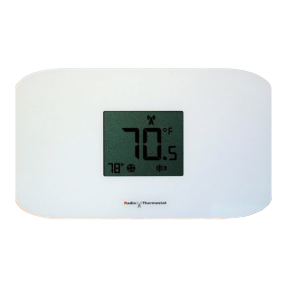
Wall Plate
and
MODE
Wall plate frame
button
Thermostat
Reset
Button
LCD screen
Z-Wave join
FAN
Button
button
Temperature
Indicators
adjust buttons
ENGLISH
Advertisement
Table of Contents

Subscribe to Our Youtube Channel
Related Manuals for Radio Thermostat CT110


Summary of Contents for Radio Thermostat CT110
- Page 1 Install Guide CT110 Caution Wall Plate Z-Wave join MODE Wall plate frame • Turn off electricity to the HVAC system before installing or Button button button servicing thermostat or any part of the system. • Do not turn electricity back on until work is completed.
- Page 2 A new location will require moving your wiring. For new installations and relocating the CT110 - follow the guidelines listed below: • Locate the thermostat on an inside wall, about 5 ft. (1.5m) above the floor, and in a room that is used often.
- Page 3 REMOVE OLD UNIT Switch OFF electricity to the HEATING and COOLING systems. Then follow these steps: • Remove cover from old thermostat. Most are snap-on types and simply pull off. Some have locking screws on the side or front. These must be loosened. DO NOT remove wires. Note the letters printed near the terminals.
-
Page 4: What Wires Do You Have
Please follow these guidelines for safe and secure wire connections: • You will need at least 2.6” of wire for each of your connections to the CT110. • If you do not have enough wire, splice additional wire to allow enough slack. - Page 5 Heat Heat/Cool Heat/Cool • The C-wire is optional but preferred. Without a C-Wire the CT110 will operate on batteries only for about one year. • Hot water systems diagrams Go To Page 15 Go To Page 15 Go To Page 16 Go To Page 16 are on pg20.
-
Page 6: Connect Your Wires
C wire is above the C terminal, 2.6" the W above the W. This allows the CT110 to fit snug to the wall. • Position the wires through the wall plate to the terminal area. - Page 7 Mark first and drill a 3/16-in.(4.8mm) hole for the insert at each screw location, then mount the unit. 1. Hold the CT110 wall plate against the wall, with the wires coming through the hole in the wall plate.
- Page 8 The CT110 will power-up in the OFF mode. Your CT110 is not configured to operate your HVAC system yet. You must now configure your thermostat for your HVAC system before you mount it to the wall plate.
- Page 9 • Always use new alkaline batteries. • Failing to replace the batteries, when necessary, could cause the thermostat to lose power or malfunction. If the thermostat loses power, then the thermostat will not control the temperature which could result in your HVAC system not functioning as you intended and lead to possible damage from overheating or excessive cooling.
- Page 10 • Use +/- buttons to select HVAC SET UP code on screen. You must select the correct HEAT type for your system. In the upper left, the CT110 will display GAS for gas heat and ELEC for Electric heat for each code.
-
Page 11: Test Installation
Snap the CT110 onto the wall plate. Take care to align with mounting posts at top and the contact pins at the bottom. With CT110 on the wall plate it is time to turn the AC power back on. Do this at the breaker you used to switch it off. -
Page 12: Communicating Thermostat
Communicating Thermostat Z-Wave join MODE The CT110 has a built in Z-Wave radio to connect you with a Button button button home automation system. This can give you access to your home’s HVAC system even when you are away. It can also give you access to web-based efficient energy management sites that can help you save money and protect the environment. - Page 13 This thermostat runs on 4AA batteries. The CT110 can be externally powered with a power source rated from 12V to 24V, AC or DC, at 100ma or greater. If used, connect to the C and RH terminals (no polarity). The 24VAC “C”...
- Page 14 This connects the heat. STEP 3 - Optional - Connect the C wire to the C terminal. THERMOSTAT TERMINAL Your heater is now connected to the CT110. Please Go To Page 6 3 Wire Heat STEP 1 - Connect the R (or RH) wire to the RH terminal. This connects HVAC SYSTEM the heat power.
- Page 15 THERMOSTAT TERMINAL STEP 5 - Optional - Connect the C wire to the C terminal. Your HVAC system is now connected to the CT110. Please Go To Page 6 W Y RH RC G 5 Wire HEAT/Cool STEP 1 - Connect the W wire to the W terminal.
- Page 16 Multi-stage Heat and Multi-stage Cool The CT110 can handle up to 2 stages of HEAT and 2 stages of COOL. HVAC SYSTEM STEP 1 - Connect the W, W2 wires to the W terminal. This connects the stages of HEAT.
- Page 17 RH G Multi-stage Heat Pump with Multi-stage Aux Heat The CT110 can handle up to 2 stages of Pump compression and 2 stages of AUX heat. STEP 1 - Connect O wire to the O terminal or B wire to the B. This connects the change-over valve.
-
Page 18: Wire Reference Table
Wire Reference Table Possible Wires What They Control R or V or VR RH and RC Single power for HEAT and COOL RH or 4 RH Power for HEAT (RH not connected to RC jumper removed) RC Power for COOL (RH not connected to RC jumper removed) W / AUX W Heat control or heat pump auxiliary heat W2 / AUX2... - Page 19 What They Control wires based on diagrams below to the correct Lennox Heat Pump terminal on the CT110. The third wire on your V or VR or R RH Power for HEAT valve may be called 6, Y, or G.
- Page 20 FCC and IC Statemen FCC Regulatory Information: NOTE: This equipment has been tested and found to comply with the limits for a Class B digital device, pursuant to Part 15 of the FCC Rules. These limits are designed to provide reasonable protection against harmful interference in a residential installation.
- Page 21 This device complies with Industry Canada’s licence-exempt RSSs. Operation is subject to the following two conditions: (1) This device may not cause interference; and (2) This device must accept any interference, including interference that may cause undesired operation of the device. Le présent appareil est conforme aux CNR d’Industrie Canada applicables aux appareils radio exempts de licence.
Need help?
Do you have a question about the CT110 and is the answer not in the manual?
Questions and answers