
Related Manuals for baxter TruSystem 7000


Summary of Contents for baxter TruSystem 7000
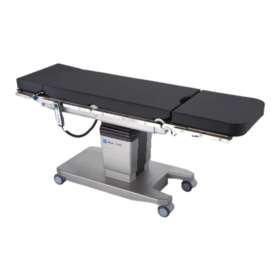
- Page 1 Instructions for use TruSystem 7000 Surgical table, universal Read the instructions for use carefully before using the ENGLISH product components and keep them safe for future reference. en-US...
- Page 2 This page is intentionally blank.
- Page 3 +49 3671 586–0 Fax: +49 3671 586–41165 surgical@hillrom.com hillrom.com Baxter Medical Systems GmbH + Co. KG is a Baxter International Inc. company. The manufacturer is hereinafter referred to as Baxter. Technical Customer Service The contact details for the current Technical Customer Service hubs in the individual countries are listed on the Internet at www.hillrom.com.
- Page 4 Supporting documents The instructions for use of the operating table and of all the products used then apply. The Baxter operating tables can be individually combined with various products. Baxter offers a wide variety of tabletop sections and accessories for an operating table.
- Page 5 © Baxter Medical Systems GmbH + Co. KG Reprinting, copying, or translating this document, in whole or in part, is forbidden without the express written permission of Baxter. All rights under copyright law are expressly reserved by Baxter. 7990044_030_10 – 2078511 – 2023-01-19...
- Page 6 TruSystem 7000 This page is intentionally blank. 7990044_030_10 – 2078511 – 2023-01-19...
-
Page 7: Table Of Contents
Combination with other products from Baxter ........ - Page 8 Contents 3.10.5 Operating tabletop with Carbon 600 / narrow Carbon 600 tabletop section ..40 3.10.6 Operating tabletop with Carbon 1200 tabletop section ......41 3.10.7 Operating tabletop with extension unit .
- Page 9 Contents 4.14 Freewheel ..............70 4.15 Running gear assistance (directional travel, turning the operating table) .
- Page 10 Contents This page is intentionally blank. 7990044_030_10 – 2078511 – 2023-01-19...
-
Page 11: Usage Specifications
Usage specifications Usage specifications Intended purpose The operating table is intended for the following use: – Patient positioning during surgical interventions including initiation and ending of anesthesia – Application-related transfer of patients within operating rooms – For use in combination with intra-surgical imaging (e.g. CT, MRT, X-ray) with special table components Contraindication Do not transport objects, devices, or materials on the operating... -
Page 12: User Definition
Usage specifications User definition The TruSystem 7000 operating table is to be operated by trained personnel only. Personnel training is carried out by the manufacturer, or by other persons accredited by the manufacturer. The primary users are medically trained, specialized personnel. -
Page 13: Service Life
Usage specifications Keep dry do not stack Service life With normal use, the service life is 10 years. 7990044_030_10 – 2078511 – 2023-01-19... -
Page 14: Safety
Baxter accepts no responsibility for the combination of the operating table with third-party products. The guarantee/warranty for products from Baxter may become void in the event of combination with third- party products. Operator’s responsibility... -
Page 15: Use Of High-Frequency (Hf) Surgical Equipment
Safety The instructions for use and the instructions provided with the medical device must be stored in a way that ensures that the user can access the information required for using the medical device at any time. The user and/or patient must report any serious incidents related to the use of the medical device to the manufacturer and the relevant authorities of the member state of which the user and/or the patient is a resident. -
Page 16: Malfunction Caused By Other Devices
– The running gear is not supported in emergency mode. The emergency mode must only be activated in case of a serious malfunction of the operating table. Please contact Baxter Technical Customer Services for the necessary repairs. The defective operating table must be barred from further use. -
Page 17: Emergency Unlocking Of The Parking Brake
All jack props [26] are immediately retracted. You can now move the operating table. Inform Baxter Technical Customer Service. No functionality is lost if the operating table had no previous defect and the emergency prop release was inadvertently activated. -
Page 18: Reset
Safety 2.7.3 Reset If the operating table reacts unexpectedly to a control, switch off the operating table and switch it back on. If you cannot even switch it off, press the reset button. The reset button [23] is located at the head end on the column base, directly below the cladding. -
Page 19: Position And Meaning
Safety 2.8.2 Position and meaning Information notice Meaning Operating table name Connector pin for equipotential bonding cable Connector socket for the mains power cable 2x 10 AT fuses Connector socket for cable remote control Before retracting the floor jacks, lower the operating table until the pictogram is covered. - Page 20 Only for the MBW operating table version Information about radio licenses For detailed information, refer to Document 7990101 (Radio Information). The column protection may only be used with the TruSystem 7000 operating table. Mark on top Not available – Not available –...
- Page 21 – Data Matrix Code – (01) Global Trade Item Number (GTIN) – (11) Date of manufacture (Year Month Day) – (21) Serial number – (240) Part number Baxter part number Serial number Medical product The device conforms to Regulation 2017/745/EU concerning medical devices.
-
Page 22: Description
Overview of the operating table 3.1.1 Operating table with two-part operating tabletop The TruSystem 7000 operating table has a two-part table top with two motor driven joint pairs (leg and back section joints) and a rigid hook coupling. Operating table movement behavior can be adjusted electrically. - Page 23 Description Column keypad Remote control Seat section Back section Motorized leg section joint with hook coupling for mount L Side rails for seat section Motorized back section joint Side rail for back section Hook coupling for S support [10] Insertion opening for traction adapter [11] Support for the extension adapter [12]...
-
Page 24: Operating Table With One-Part Operating Tabletop
Description 3.1.2 Operating table with one-part operating tabletop The TruSystem 7000 U14 operating table has a one-part tabletop with two motorized joint pairs (leg and back section joint). Operating table movement behavior can be adjusted electrically. The operating table has an electrical drive unit. -
Page 25: Column Protection (Cladding Protection Ts7000, #2069528)
Description [14] Equipotential bonding cable connector pin [15] Connector socket for power cable [16] Wheel [17] Fifth wheel for running gear assistance (directional travel/ drive mode) [18] Running gear emergency release button (under the label) [19] Mains power cable [20] Equipotential bonding cable [21] Head end of the operating table... -
Page 26: Summary Of Control Modules
Description Summary of control modules The operating table can be adjusted using the following control modules: – Column keypad The column keypad allows you to use the basic functions of the operating table. – Remote control The remote control is absolutely necessary for using the operating table to its full potential. - Page 27 Description EM RGENCY OVE RI E [i1] Switch on the operating table, indicator: Ready [i2] Switching off the operating table [i3] Head position left, indicator: Head position left [i4] Head position right, indicator: Head position right [i5] Lift up [i6] Lower [i7] Trendelenburg...
-
Page 28: Remote Control
Description 3.3.2 Remote control TruSystem 7000 cable remote control: [30] Touchscreen [i30] Cancel or go back up to the previous level in the menu [i31] OK - Confirm a selected menu function and return to the main menu [i45] Lock operating table... -
Page 29: Hook Couplings
Description [i2] Switching off the operating table [i11] Level position [i12] Raise leg section joints [i13] Lower leg section joints [i14] Raise back section joints [i15] Lower back section joints [i16] Longitudinal travel toward head end [i17] Longitudinal travel toward foot end [i24] Select left joint [i25] Select right joint The handling behavior cannot be controlled with the TruSystem... -
Page 30: Side Rails
Chapter 3.1. Side rails The operating tabletop is equipped with side rails. Accessories can be attached to the side rails. The accessories approved by Baxter are listed in the Compatibility Matrix . The accessories must be taken into account when determining the total patient weight. -
Page 31: Setting Options
Description Setting options 3.7.1 Patient orientation For the motor functions on the operating table, the operating table must be aware of the patient's current head position on it. Only if the indicator on the column keypad matches the orientation of the patient on the operating table will the operating table's functions be carried out on the correct side. -
Page 32: Tilt
Description 3.7.3 Tilt The operating tabletop is tilted around its longitudinal axis to the left [A] or right [B]. The side specification is based on the user's perspective when standing at the head end of the patient. 3.7.4 Trendelenburg The operating tabletop is moved electrically around its transverse axis. -
Page 33: Back Section Joints (Operating Table With One-Part Operating Tabletop)
Description 3.7.7 Back section joints (Operating table with one-part operating tabletop) The joints are inclined electrically upward [A] or downward [B]. 3.7.8 Leg section joints The joints are inclined electrically upward [A] or downward [B]. The joints can only be moved together with the column keypad. With the remote control, when the normal patient orientation is selected, the right and left joints can be moved independently of each other. -
Page 34: Visual Displays And Indicators
Description Visual displays and indicators Display Status Color Meaning Action Ready [i1] Illuminated green Operating table is switched on – and ready to use. Flashing green In addition to indicator [i1], the See indicator [i20] emergency mode indicator is illuminated. –... - Page 35 Description Display Status Color Meaning Action Emergency operation [i20] Illuminated in red In addition to indicator [i20], the Block the defective operating operational readiness indicator table from use for subsequent [i1] flashes. operations. The operating table emergency Inform the Technical mode was activated manually.
-
Page 36: Sounds
– Emergency mode In addition to the acoustic signals, a corresponding indicator is shown in the display when using the TruSystem 7000 remote control device. 7990044_030_10 – 2078511 – 2023-01-19... -
Page 37: Load Capacity Of Operating Table With Two-Piece Operating Tabletop
450 kg / 992 lbs. The maximum load may only be applied to the operating table if the conditions in Chapter 3.10 are met. Consult Baxter regarding the permissible load in any configuration of the operating table other than that described in these instructions for use. -
Page 38: Operating Tabletop With Head Section And Leg Section
Description movement to bring the operating table with its current load back into a safe range. If the operating table load is exceeded, an error message is shown on the remote control display. Only the flashing evasive movement is permitted on the operating table. Example: When checking the operating table load, the electronics system detects a head-end overload of the operating table. -
Page 39: Operating Tabletop With Head Section And Universal Section
Description 3.10.2 Operating tabletop with head section and universal section Version 1 A head section is [A] attached at the head end of the operating tabletop. The universal section [B] is attached at the foot end of the operating tabletop. Normal patient orientation is active on the operating table. -
Page 40: Operating Tabletop With Seat Section Extension, Upper Back Section And Head
Description 3.10.4 Operating tabletop with seat section extension, upper back section and head section No tabletop section is required at the head end of the operating tabletop. A seat section extension [A], an upper back section [B] and a head section are [C] attached at the foot end of the operating tabletop. -
Page 41: Operating Tabletop With Carbon 1200 Tabletop Section
Description 3.10.6 Operating tabletop with Carbon 1200 tabletop section No tabletop section may be attached to the head end of the operating tabletop. A Carbon 1200 tabletop section is [A] attached at the foot end of the operating tabletop. The orientation of the patient on the operating tabletop is normal or inverted. -
Page 42: Operating Tabletop With Pediatric Extension Section
Description 3.10.9 Operating tabletop with pediatric extension section No tabletop section is required at the head end of the operating tabletop. The pediatric extension section [A] is attached at the foot end of the operating tabletop. The patient orientation on the operating table is switched to inverted. -
Page 43: Load Capacity Of Operating Table With One-Piece Operating Tabletop
450 kg / 992 lbs. The maximum load may only be applied to the operating table if the conditions in Chapter 3.10 are met. Consult Baxter regarding the permissible load in any configuration of the operating table other than that described in these instructions for use. -
Page 44: Operating Tabletop With Head Section, Upper Back Section And Universal Section
Description movement to bring the operating table with its current load back into a safe range. If the operating table load is exceeded, an error message is shown on the remote control display. Only the flashing evasive movement is permitted on the operating table. Example: When checking the operating table load, the electronics system detects a head-end overload of the operating table. -
Page 45: Operating Tabletop With Head Section, Upper Back Section And Leg Section
Description 3.11.3 Operating tabletop with head section, upper back section and leg section An upper back section [A] and a head section [B] are attached at the head end of the operating tabletop. A leg section is [C] attached to the foot end of the operating tabletop. -
Page 46: Operating Tabletop With Carbon 600 / Carbon 600 Narrow Tabletop Section
Description 3.11.5 Operating tabletop with Carbon 600 / Carbon 600 narrow tabletop section and leg section A leg section [A] is attached at the head end of the operating tabletop. A Carbon 600 / Carbon 600 narrow tabletop section [B] with X-RAY head-positioning accessory [C] is fastened to the foot end of the operating tabletop. -
Page 47: Operating Tabletop With Extension Unit
Description 3.11.7 Operating tabletop with extension unit The extension unit [A] is attached at the foot end of the operating tabletop. The orientation of the patient on the operating tabletop is normal. Permissible load: 160 kg / Patient weights of up to 160 kg / 352 lbs are possible 352 lbs without any restrictions applying to the operating table functions. -
Page 48: Operating Tabletop With Ophthalmological Adapter And Leg Sections
Description 3.11.10 Operating tabletop with ophthalmological adapter and leg sections The ophthalmological adapter [A] is attached at the head end of the operating tabletop. Accessories for head positioning can be attached to the ophthalmological adapter. Leg sections [B] are attached at the foot end of the operating tabletop. -
Page 49: Loading The Side Rails
Description 3.12 Loading the side rails WARNING Risk of personal injury and material damage when exceeding permissible loads • Regardless of the permitted load capacity of the individual side rails, the one-sided total torque around the longitudinal axis of the operating table may not exceed 100 Nm / 73 ft·lb during normal use. -
Page 50: Use In Imaging System
Description 3.13 Use in imaging system The tabletop is fully radiolucent between the struts. Avoid wrinkling the pad and other materials lying on it (towels, underlays) in order to keep image artifacts to a minimum. The cladding protection is not radiolucent. X-ray area of the operating tabletop: X-ray area, foot end X-ray area, head end... -
Page 51: External Power Supply (Line Connection)
Description The battery charge status can be seen on the indicator [a1] on the column keypad. Observe the indicator while using the operating table. If the batteries are completely discharged, recharging will take approximately 3 hours. Indicator [a1] on the column keypad lights green when the batteries are fully charged. -
Page 52: Software Settings
Speed, drive unit: This function enables individual adjustment of the speed of the drive unit for the operating table version MB/MBW. The desired option has to be adjusted on site by the Baxter Technical Customer Service or the responsible hospital technician. -
Page 53: Use
– Risk of injury due to protruding parts. Keep sufficient distance. – Use of the operating table is permitted in combination with other products from Baxter. The instructions for use of the products used must be observed and followed when the products are used. - Page 54 Transport/repositioning: – Occupational safety for personnel: Given their heavy weight, take extra care not to strain your back when lifting or carrying the tabletop sections and accessories, or when manually adjusting the operating table with or without a patient. Work with an additional person if necessary.
- Page 55 – The pads can be removed. Only use the appropriate pads made by Baxter. Do not position the patient on the operating table without a pad. – Lift the patient into the desired position on the operating table;...
-
Page 56: Unpacking And Setting Up The Operating Table
– Do not stick any sharp-edged objects into the pad. Avoid placing sharp objects on the pad. Do not attach any adhesive film. Unpacking and setting up the operating table The operating table comes delivered in cardboard packaging, on a pallet. -
Page 57: Selection Of Functions
Release the key lock. Press key [i53] for this. The release of the keypad is indicated by an audible signal and the associated indicator lights up. The keypad is released for operation for 10 seconds. Operating table lock (jacks extended) Press key [i45] until an intermittent audible signal is heard. -
Page 58: Blocked Keys
The safety of the operating table is only guaranteed with the original mains power cable. • The operating table must be used with the original mains power cable from Baxter only. • Do not extend the mains power cable on the operating table. 7990044_030_10 – 2078511 – 2023-01-19... -
Page 59: Connecting / Disconnecting The Equipotential Bonding Cable
Connecting the cable: Flip up the connector socket cover [15] on the running gear [13] and insert the power cable plug [19] into the socket as shown [15]. The connection location is identified by the symbol for the power supply connection. Route the cable such that no one can trip or fall over it. -
Page 60: Attaching/Removing The Column Cladding Protection
Attaching/removing the column cladding protection CAUTION Danger of crushing fingers between the two cladding protection parts • Do not reach between the two cladding protection parts during transport, storage and assembly of the column protection. Magnets are located at the ends of the cladding protection parts for assembly purposes. -
Page 61: Attaching Accessories To The Side Rail
CAUTION! Risk of crushing injury to fingers. Do not touch the tabletop section at the hooks. Hang the tabletop section with the hooks in the fixing points on the operating tabletop. The interlock must audibly lock. Check that the tabletop section is securely fastened to the operating tabletop. -
Page 62: Operating States
Operating states 4.9.1 Switching on the operating table Press the ON [i1] key on the column keypad. Indicator [i1] on the column keypad lights up and an audible signal sounds after a few seconds. The operating table is only ready for use once the signal tone has sounded. -
Page 63: Lift
4.10.2 Lift CAUTION Risk to patients due to collision Risk of crushing for the user When lowering the operating tabletop, collisions may occur with the running gear, the floor, furnishings or devices located below the operating tabletop. • Clear the area beneath the table top or raise the corresponding tabletop sections (leg/back section joints). -
Page 64: Trendelenburg
4.10.4 Trendelenburg CAUTION Risk to patients due to collision Risk of crushing for the user When tilting the operating tabletop, collisions may occur with the column, the floor, the furnishings or the devices beneath the tabletop that may be covered by draping or underlays. •... -
Page 65: Back Section / Back Section Joints
Restrictions: Longitudinal travel is automatically restricted or locked in the following situations. The longitudinal travel is locked once the extension adapter is hooked onto the operating tabletop. The presence sensor is active. The longitudinal travel may be limited if the leg section joints or lower back section joints are inclined downward. -
Page 66: Leg Section Joints Together
4.10.7 Leg section joints together There are side rails on the leg section joints of the operating table (not an option for the U-version of the operating table). When adjusting the leg section joints, accessories connected to the side rail are thus also repositioned. Arrange the accessory on the operating table in such a manner that it does not collide with another accessories, tabletop sections or the operating table during positioning. -
Page 67: Level Position
Select the joint on the remote control. To do this, press the [i24] key for the left joint or the [i25] key for the right joint. Only the display of the selected leg section lights up. Move the joint upward using the [i12] key or downward using the [i13] key. -
Page 68: Flex Down / Flex Up
4.10.10 Flex down / flex up The function can only be selected with the remote control. Flex up: Press the [i32] key on the remote control. Flex down: Press the [i33] key on the remote control. 4.11 Requirements for unlocking, rotating, and moving the operating table WARNING Risk of personal injury when transporting patients due to tipping of the operating table! -
Page 69: Locking The Operating Table (Activating The Parking Brake Jacks)
4.12 Locking the operating table (activating the parking brake jacks) The brake prevents the operating table from rolling away. Feet [26] automatically extend at all four wheels to ensure the operating table maintains a stable position. CAUTION Hazard to the patient •... -
Page 70: Freewheel
Prepare the operating table according to the conditions on page 68. Press key [i52] or [i54] until an audible signal sounds. The signal will sound intermittently until the operating table jacks are fully retracted and the additional wheel [17] in the middle under the running gear is extended. -
Page 71: Running Gear Assistance (Directional Travel, Turning The Operating Table)
4.15 Running gear assistance (directional travel, turning the operating table) Running gear assistance supports directional movement or the turning of the operating table on the spot. Transverse travel of the operating table is not possible. CAUTION Risk of personal injury due to crushing •... -
Page 72: Patient Positioning
CAUTION Risk of personal injury due to crushing • Do not allow the feet to get caught in the running gear recess when moving the operating table. Note the crush hazard symbol on the running gear! NOTICE Risk of damage to goods due to collisions •... -
Page 73: Decommissioning
For temporary decommissioning, continue to charge the batteries regularly to ensure that battery life is maintained. Baxter recommends a charging interval of 1 month. Store the operating table and corresponding tabletop sections in a room designated for this purpose. -
Page 74: Cleaning And Disinfection
The disinfection kills or inactivates pathogens, thus infection is no longer probable. Baxter has verified the procedures described in this section to confirm their effectiveness in principle. Other methods may be used for cleaning and disinfection, although their effectiveness must be checked by the operator. -
Page 75: Summary Of Cleaning And Disinfection
The scope, timing and procedure used for cleaning and disinfection is determined by the operator. In these instructions for use, Baxter describes how the operating table can be manually cleaned and disinfected. Before each use, the user must ensure that the operating table has been cleaned and disinfected. -
Page 76: Cleaning The Operating Table
Cleaning and disinfection Move the operating table to the level position with the [i11] key. Press the key until the operating table stops automatically. An audible signal then sounds. Move adjustable tabletop sections to a horizontal position by hand. Adjust the height of the operating table with the [i5] or [i6] key so that the work does not strain your back. - Page 77 Cleaning and disinfection Clean all residues from the uppermost side of the pad. Wipe the sides of the pad again. Leave the pads on the resting surface until dry. Also ensure that the Velcro tape is completely dry. Wipe the surface of the operating tabletop and the individual tabletop sections so there are no residues.
- Page 78 Cleaning and disinfection Clean the hook couplings at the head end of the operating table to remove all residues. Move the adjustable hook couplings all the way up and clean them to remove all residues. Then move the hook couplings all the way down and clean again so there are no residues.
-
Page 79: Disinfecting The Operating Table
Cleaning and disinfection 22. Clean the bellows and sheet metal casing from all sides so there are no residues. 23. Clean the running gear thoroughly from above so there are no residues. 24. Visually inspect the surfaces of the entire operating table. The surfaces must be free of residue and any visible contamination. - Page 80 Cleaning and disinfection Disinfect the surface of the operating table, including the tabletop sections. Allow the surface to dry. Once the underside of the pads is dry, place the pads with the disinfected side facing downward on the additionally disinfected resting surface. Disinfect the uppermost side of the pad.
- Page 81 Cleaning and disinfection Extend the operating tabletop with the [i17] key all the way to the foot end. i17 i17 Disinfect the extended operating tabletop from underneath. Move the operating tabletop with the [i5] key all the way up. Disinfect the bellows and panel cladding from all sides. Disinfect the running gear from above.
-
Page 82: Troubleshooting
If an error recurs or cannot be resolved, take the device out of service and inform the Technical Customer Service of Baxter. In case of an error during the operation of the operating table, the user might be prompted to restart the operating table. - Page 83 Troubleshooting Error Possible cause Correction Operating table cannot be The operating table or the Contact Technical Customer charged, the battery status battery is defective Service indicator flashes (Reverse) Trendelenburg position The tilt angle setting is too high Reduce the tilt cannot be fully attained Tilt position cannot be fully The (reverse) Trendelenburg...
-
Page 84: Maintenance
Product maintenance must be carried out by qualified service technicians only. The contact details of service technicians can be obtained from the Technical Customer Service at Baxter. Baxter recommends concluding a maintenance agreement, so that maintenance can be carried out promptly and reliably. -
Page 85: Disposal
If you have any questions about proper disposal, please contact the Technical Customer Service at Baxter, your local dealer, or the appropriate national authority. In addition to regional disposal, faulty or obsolete products can be returned to Baxter. -
Page 86: Technical Data
Technical data Technical data 10.1 Operating table Dimensions Length of the operating tabletop (from Operating table with two-part operating one hook coupling to the next) tabletop: 1248 mm / 49.13 inch [A] Operating table with one-part operating tabletop: 843 mm / 33.19 inch [B] Width [C] of the operating tabletop with 601 mm / 23.66 inch side rails according to European standard... - Page 87 Technical data Weight/load Loading of side rail Longitudinal axis: each 100 Nm / each 73 ft·lb Transverse axis: each 150 Nm / each 110 ft·lb Outer packaging Cardboard, wood, plastic bag and metal parts: 80 kg / 176 lbs Setting ranges Lift –...
-
Page 88: Svhc (Substance Of Very High Concern)
According to Article 33 of the REACH regulation (EC) no. 1907/2006, the products may contain components with reportable substances in concentrations exceeding 0.1 mass percent. A list of affected components will be provided by Baxter on request. The list can also be viewed online at ois.hillrom.com/ ois. -
Page 89: Electromagnetic Compatibility
Table 1 according to IEC 60601-1-2:2014 Guidelines and manufacturer's declaration – electromagnetic interference The TruSystem 7000 operating table is intended for use in the electromagnetic environments as specified below. The customer or user of the aforementioned operating table must ensure that it is operated in an environments as described. - Page 90 Do not use portable RF communications equipment (including peripherals such as an antenna cable and external antennas) at a distance of less than 30 cm (12 in) from the TruSystem 7000 operating table, including its cables that have been specified by the manufacturer. Otherwise, the functionality of the system may be impaired.
- Page 91 Technical data The TruSystem 7000 operating table satisfies the following EN/ EC 60601-1-2 test levels with the specified compliance levels; the customer or user of the TruSystem 7000 lighting system should ensure that it is being used in such an environment.
- Page 92 EMC-relevant wireless properties of the operating table Notice: Interference caused by other devices The TruSystem 7000 operating table may be subject to interference from other devices, even if these devices comply with the applicable CISPR-defined emission requirements. 7990044_030_10 – 2078511 – 2023-01-19...
-
Page 93: Product Certification
Regulation 2017/745/EU concerning medical devices, and is compliant with the version of the regulation currently in force at the time of product sale. Baxter declares the conformity of the operating table with the essential safety and performance requirements according to Regulation 2017/745/EU concerning medical devices, Annex I. -
Page 94: Radio License (Only For Mbw Operating Table Version)
Radio license (only for MBW operating table version) Radio license (only for MBW operating table version) Radio license information is listed in Document 7990101 (Radio information). 7990044_030_10 – 2078511 – 2023-01-19... - Page 95 This page is intentionally blank.
- Page 96 7990044_030_10 – 2078511 – 2023-01-19...
Need help?
Do you have a question about the TruSystem 7000 and is the answer not in the manual?
Questions and answers