
Subscribe to Our Youtube Channel
Related Manuals for PIETRO FIORENTINI RSE 1,2 LA N1


Summary of Contents for PIETRO FIORENTINI RSE 1,2 LA N1
- Page 1 RSE - RSV Diaphragm smart meter Revision 00 - Edition 12/2022 USE, MAINTENANCE USE, MAINTENANCE AND WARNING AND WARNING MANUAL MANUAL...
- Page 2 pagE iNtENtiONaLLY LEFt BLaNK DiaphRagm smaRt mEtER iNtRODUCtiON REV. 00 Use, maintenance and warning instructions Use, maintenance and warning instructions...
-
Page 3: Introduction
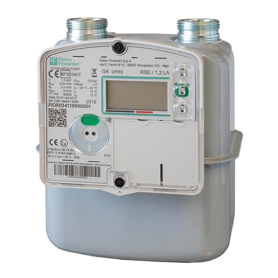
NOTICE! The images shown in this document indicate the type of product and may differ in detail. Revision: 00 COPYRIGHT 2022 © PIETRO FIORENTINI S.P.A. DiaphRagm smaRt mEtER iNtRODUCtiON REV. 00 Use, maintenance and warning instructions... - Page 4 pagE iNtENtiONaLLY LEFt BLaNK DiaphRagm smaRt mEtER iNtRODUCtiON REV. 00 Use, maintenance and warning instructions...
-
Page 5: Revision History
1.1 - REVISION HISTORY Revision Date Revision contents index 12/2022 First issue Tab. 1.1. DiaphRagm smaRt mEtER iNtRODUCtiON REV. 00 Use, maintenance and warning instructions... -
Page 6: Table Of Contents
INDEX 1 - INTRODUCTION ........................3 1.1 - REVisiON histORY ..........................5 2 - GENERAL INFORMATION ....................11 2.1 - maNUFaCtURER iDENtiFiCatiON ......................11 2.2 - iDENtiFiCatiON OF thE pRODUCt ...................... 11 2.3 - REgULatORY FRamEWORK ......................... 12 2.4 - WaRRaNtY ............................12 2.4.1 - REFERENCE OpERatiNg CONDitiONs ....................13 2.5 - aDDREssEEs, sUppLY aND stORagE OF thE maNUaL .............. - Page 7 4 - DESCRIPTION AND OPERATION ..................33 4.1 - gENERaL DEsCRiptiON ........................33 4.1.1 - pOWER sUppLY DEViCEs ........................34 4.1.1.1 - CONNECtiON OF thE pOWER sUppLY DEViCEs ..............34 4.1.1.2 - pOWER sUppLY statUs ......................34 4.1.2 - shUt-OFF VaLVE (OptiONaL) ......................35 4.1.3 - aCQUisitiON OF thE mEasURE ......................35 4.1.4 - EVENts aND DiagNOstiCs ........................36 4.1.5 - aCtiVatiON aND CONFigURatiON.....................36...
- Page 8 5.5.17 - CONVENtiONaL maXimUm CURRENt FLOW RatE (END OF pREViOUs pERiOD) ......49 5.5.18 - CURRENt FEE sChEmE iDENtiFiER ....................49 5.5.19 - pREViOUs FEE sChEmE iDENtiFiER ....................49 5.5.20 - statUs OF thE DEViCE ........................50 5.5.20.1 - sERViCE sUB-mENU ........................50 5.5.21 - DatE ..............................51 5.5.21.1 - FiRmWaRE sUB-mENU .......................51 5.5.22 - hOUR ..............................52 5.5.23 - CURRENt RatE ...........................52...
- Page 9 9 - MAINTENANCE AND FUNCTIONAL CHECKS ..............73 9.1 - gENERaL WaRNiNgs ........................... 73 9.2 - spECiaL maiNtENaNCE ........................74 9.2.1 - REpLaCiNg thE COmmUNiCatiON BattERY paCK .................74 9.2.2 - sim REpLaCEmENt (gpRs aND NBiOt VERsiONs ONLY) ..............77 9.3 - mEtROLOgiCaL VERiFiCatiONs iN thE LaBORatORY ..............79 9.3.1 - REQUiREmENts FOR sEttiNg Up thE tEst ..................79 9.3.2 - tEst pROCEDURE ..........................80 10 - UNINSTALLATION AND DISPOSAL .................
- Page 10 PAGE INTENTIONALLY LEFT BLANK DiaphRagm smaRt mEtER iNtRODUCtiON REV. 00 Use, maintenance and warning instructions...
-
Page 11: General Information
2.2 - IDENTIFICATION OF THE PRODUCT Equipment Diaphragm smart meter Series rse - rsV • rse 1,2 La N1 • rse / 1,2 La rF169 • rse / 1,2 La gprs • rse 2,4 La N1 Available models •... -
Page 12: Regulatory Framework
FiOreNtiNi s.p.a. guarantees that the equipment was manufactured using the best materials, with high quality workmanship, and complies with the quality requirements, specifications and performance set out in the order. The warranty shall be considered null and void and pietrO FiOreNtiNi s.p.a. shall not be liable for any damage and/or malfunctions: •... -
Page 13: Reference Operating Conditions
2.4.1 - REFERENCE OPERATING CONDITIONS The reference operating conditions to calculate the life span of the batteries are described in the UNI/TS 11291-11-1 and 11291-12-1 standards. An extract of these standards is found in Tab. 2.4.: Operative Reference indications condition Display: 10 minutes per month. -
Page 14: Addressees, Supply And Storage Of The Manual
Removing, rewriting or modifying the pages of the manual and their contents is not allowed. PIETRO FIORENTINI S.p.A. shall not be held liable for any damage to people, animals and property caused by failure to adhere to the warnings and operating procedures described in this manual. -
Page 15: Symbols Used In The Manual
2.7 - SYMBOLS USED IN THE MANUAL Symbol Definition Symbol used to identify important warnings for the safety of the operator and/or equipment. Symbol used to identify information of particular importance in the instruction manual. The information may also concern the safety of the personnel involved in using the equipment. Obligation to consult the instruction manual/booklet. -
Page 16: Nameplates Applied
M2/E2 15 °C OIML R137-1&2:2012 20YY EN 1359:1998/A1:2006 FIOR0344YYXXXXXX Utilizzare solo pacchi batterie sostituibili Pietro Fiorentini rse / 1.2 La g4 N1 tipo identificativo: D09 Tipo identificativo apparato: A14 3G Ex ic IIB T3 Gc EPTI 17 ATEX 0260 X... - Page 17 M2/E2 15 °C OIML R137-1&2:2012 20YY EN 1359:1998/A1:2006 FIOR0341YYXXXXXX Utilizzare solo pacchi batterie sostituibili Pietro Fiorentini rse / 1.2 La g4 gprs tipo identificativo: D09 Tipo identificativo apparato: A14 3G Ex ic IIB T3 Gc EPTI 17 ATEX 0260 X...
- Page 18 -25 °C ≤ T ≤ +55 °C Avvertimento: Potenziale pericolo di cariche elettrostatiche - vedere le istruzioni Pietro Fiorentini S.p.A. via E. Fermi 8/10 - 36057 Arcugnano (VI) - Italy OIML R137-1&2:2012 EN 1359:1998/A1:2006 I-2142-MI002-TG007 RSV / 1,2 LA N1...
-
Page 19: Identifier Of The Logic Device
2.8.1 - IDENTIFIER OF THE LOGIC DEVICE Term Description Format FiO-r-03-WV-YY-XXXXXX. Fixed field indicating the manufacturer (PIETRO FIORENTINI S.p.A.) according to the encoding of the Flag Association. Type of meter: RSE/RSV. Type of device (03=Gas Meter). Type of gauge. Remote communication type. -
Page 20: Description Of The Nameplates
15 °C "T" "H3" M2/E2 15 °C OIML R137-1&2:2012 20YY EN 1359:1998/A1:2006 FIOR0344YYXXXXXX Utilizzare solo pacchi batterie sostituibili Pietro Fiorentini tipo identificativo: D09 Tipo identificativo apparato: A14 3G Ex ic IIB T3 Gc EPTI 17 ATEX 0260 X 1054 IP55 -25 °C ≤... -
Page 21: Glossary Of Measurement Units
2.9 - GLOSSARY OF MEASUREMENT UNITS Type of measurement Unit of measurement Description sm³/h Standard cubic metres per hour sm³ standard cubic metres Consumption and Volumetric flow rate m³/h Cubic metres per hour m³ Cubic metres Pressure ˝wc Water column inch Pascal °C Degree centigrade... -
Page 22: Qualified Professional Figures
2.10 - QUALIFIED PROFESSIONAL FIGURES Qualified operators in charge of using and managing the equipment throughout its technical service life to be used as indicated: Professional figure Definition Qualified operator able to: • handle materials and equipment. • carry out all the operations necessary to properly install the equipment; Installer •... -
Page 23: Safety
3 - SAFETY 3.1 - GENERAL SAFETY WARNINGS WARNING! The equipment described in this manual is normally installed in systems which transport flammable gases (for example natural gas). WARNING! If the gas used is a combustible gas, the installation area of the equipment is defined as a “danger zone” as there are residual risks that potentially explosive atmospheres may be generated. -
Page 24: Atex Directive Safety Instructions
Further information can be found in EN60079-32-1: among the possible actions, an example is using dissipative footwear and a damp cloth (%>65%) during installation/maintenance operations. NOTICE! PIETRO FIORENTINI S.p.A. disclaims any liability resulting from the risks and consequences caused by non-compliance with these provisions. 3.2.2 - CONNECTING TO OTHER DEVICES the rse - rsV meters can be connected: •... -
Page 25: Safety Instructions For Installation In Hazardous Area
NOTICE! PIETRO FIORENTINI S.p.A. shall not be liable for damage resulting from failure to comply with the instruc- tions and from misuse. safety warnings All operations on the device must be performed by qualified personnel. -
Page 26: Personal Protective Equipment
3.3 - PERSONAL PROTECTIVE EQUIPMENT The following table shows the Personal Protective Equipment (PPE) and its description; an obligation is associated with each symbol. personal protective equipment means any equipment intended to be worn by the worker in order to protect them against one or several risks that are likely to threaten their safety or health during work. -
Page 27: Obligations And Prohibitions
3.4 - OBLIGATIONS AND PROHIBITIONS the following is a list of obligations and prohibitions to be observed for the safety of the operator: it is mandatory to: • carefully read and understand the use, maintenance and warning manual; • before installing the equipment, strictly refer to the details specified on the nameplates and in the manual; •... -
Page 28: Residual Risks
WARNING! If there are any functional faults, do not operate. Immediately contact PIETRO FIORENTINI S.p.A. for the necessary directions. 3.5.1 - POTENTIAL DANGER OF ELECTROSTATIC CHARGES This device is approved for installation in areas with low explosion risk (risk is only present for short periods). -
Page 29: Safety And Fraud Prevention
3.6 - SAFETY AND FRAUD PREVENTION the solutions implemented on the equipment to assure safety comply with the requirements set forth by the reference standard in force (UNI/TS 11291). In detail, access is not possible: • to the electronics without the removal of the mechanical metrological seals and thus without permanent damage to the metrological cover in accordance with the Type Examination Certificate (MID) legalisation plan of the meter;... -
Page 30: Seals
• the duration of the conditions is monitored and recorded by the firmware. Fig. 3.2. Anti-fraud security RSE - RSV 3.6.1 - SEALS The PIETRO FIORENTINI S.p.A. equipment has the following seals described in Tab.3.17: Symbol Type Description screw cover seal... -
Page 31: Safety Pictograms
3.7 - SAFETY PICTOGRAMS The safety pictograms described in Tab.3.17 may be shown on the equipment and/or packaging PIETRO FIORENTINI S.p.A.: Symbol Definition Symbol used to identify a GENERIC HAZARD. symbol used to identify DaNgers geNerateD BY statiC eLeCtriCitY. symbol applied to the packaging to identify the type of danger and risks related to the transport- ed product, based on the classification of the European ADR agreement. - Page 32 PAGE INTENTIONALLY LEFT BLANK Diaphragm smart meter saFetY reV. 00 Use, maintenance and warning instructions...
-
Page 33: Description And Operation
4 - DESCRIPTION AND OPERATION 4.1 - GENERAL DESCRIPTION The RSE - RSV apparatus is a volumetric meter that is applied at the gas distribution networks final redelivery points. The meter incorporates a diaphragm measuring system to measure the volume of gas flowing through it, which can: •... -
Page 34: Power Supply Devices
4.1.1 - POWER SUPPLY DEVICES The equipment RSE - RSV can only be powered by the specific approved battery packs. The device uses two distinct battery packs: • the metrological battery which cannot be replaced in the field, useful for managing the metrological part and local interfaces;... -
Page 35: Shut-Off Valve (Optional)
4.1.2 - SHUT-OFF VALVE (OPTIONAL) NOTICE! The gas flow shut-off valve is not accessible without causing permanent damage to the meter. The gas flow shut-off valve is found inside the body of the meter in the inlet fitting, which intercepts the gas flow to the utility for commercial purposes only. -
Page 36: Events And Diagnostics
4.1.4 - EVENTS AND DIAGNOSTICS With reference to the standards of the UNI/TS 11291 series, the equipment implements in particular the following services: • detection and reporting of faults (UNI/TS 11291-1); • functional requirements - events log (UNI/TS 11291-6); • functional requirements - diagnostics and alarms (UNI/TS 11291-6). -
Page 37: Intended Use
If no written approval is provided, use shall be considered “improper”. In the event of “improper use”, PIETRO FIORENTINI S.p.A. shall not be held liable for any damage caused to people or property, and any type of warranty on the equipment shall be deemed void. -
Page 38: Technical Data
4.3 - TECHNICAL DATA General features Electronic casing/Container Polycarbonate Casing protection rating IP55 ISO 228, 1"1/4, also available with connections: 3/4'', 7/8'', 1'', Threaded fitting/Connections and 2'' single coupling Resistance to high temperatures “T” 1359:1998/A1:2006 Maximum working pressure 0.5 bar Operative temperature range from -25 °C to +55 °C Gas temperature range... -
Page 39: User Interface
5 - USER INTERFACE 5.1 - GENERAL DESCRIPTION the following paragraphs describe the interaction methods between operator and user interface, and the meanings of the various fields on the display. the user interface consists of the following main components, through which it is possible to consult the data provided by the device (see Fig.5.4.): Pos. -
Page 40: Lcd Display Description
5.2 - LCD DISPLAY DESCRIPTION NOTICE! To assure a long battery life, the display is usually kept off. With the display off, turn it on by pressing the “Enter” key for at least 1 s. The display automatically switches off after 2 minutes of inactivity. Fig. -
Page 41: Menu Field
5.2.1 - MENU FIELD Icon Description Volume totaliser at the reference conditions. Volume totaliser in alarm. Volume totaliser under reference conditions for range 1. Volume totaliser under reference conditions for range 2. Volume totaliser under reference conditions for range 3. Totalisers T, TA, T1, T2 , T3 concerning previous billing period. -
Page 42: Icons And Alarms Field
5.2.3 - ICONS AND ALARMS FIELD Fig. 5.6. Icons and alarms field Tab. 5.29. describes the icons present: Pos. Name Description Communication When active, indicates a remote communication session in progress. When the icon is: • on and steady, it indicates the presence of an alarm condition. The alarm has been recorded and is currently present;... -
Page 43: Start-Up Procedure
5.3 - START-UP PROCEDURE Under normal operating conditions, the display is completely off. Tab. 5.30. shows the procedure for switching on the interface: Step Action Press the green 'Enter' button to switch on the display. NOTICE! Upon switch-on, a 'lamp test' is performed, lasting approximately 3 sec., during which all fields will be lit to check for faulty segments or icons. -
Page 44: Sequence Of Available Menus
5.5 - SEQUENCE OF AVAILABLE MENUS The menu display sequence is circular. Once the end is reached, the display continues in the order defined below. 5.5.1 - VOLUME TOTALISER AT THE REFERENCE CONDITIONS Abbreviation Format Unit Sub-menu Image on Display 5 integer digits and 3 decimal m³... -
Page 45: Volume Totaliser In Tariff Range 3
5.5.5 - VOLUME TOTALISER IN TARIFF RANGE 3 Abbreviation Format Unit Sub-menu Image on Display 5 integer digits and 3 decimal m³ digits Tab. 5.35. 5.5.6 - VOLUME TOTALISER AT REFERENCE CONDITIONS (END OF PREVIOUS PERIOD) Abbreviation Format Unit Submenu Image on Display 5 integer digits T PRE... -
Page 46: Volume Totaliser In Tariff Range 3 (End Of Previous Period)
5.5.10 - VOLUME TOTALISER IN TARIFF RANGE 3 (END OF PREVIOUS PERIOD) Abbreviation Format Unit Sub-menu Image on Display 5 integer digits T3 PRE and 3 decimal m³ digits Tab. 5.40. 5.5.11 - PERIOD END DATE Abbreviation Format Unit Sub-menu Image on Display dd-mm-yy Tab. -
Page 47: Diagnostics
5.5.12 - DIAGNOSTICS Abbreviation Format Unit Sub-menu Image on Display 4 digits (Hexa- decimal Code) Tab. 5.42. The coding of the information complies with what is defined in UNI/TS 11291-11/-12. The 16 bits shown in Tab. 5.43. are represented in hexadecimal format (0 - F) in groups of 4: Format Description groups... -
Page 48: User Message
5.5.13 - USER MESSAGE Abbreviation Format Unit Sub-menu Image on Display Text (max. 100 characters) Tab. 5.45. 5.5.14 - REDELIVERY POINT (PDR) ID Abbreviation Format Unit Sub-menu Image on Display 14 digits “e” Tab. 5.46. Press the green 'Enter' key to activate the scroll mode and check the 14-character Redelivery Point (PDR) field. 5.5.15 - VALVE STATUS Abbreviation Format... -
Page 49: Maximum Conventional Flow Rate
5.5.16 - MAXIMUM CONVENTIONAL FLOW RATE Abbreviation Format Unit Sub-menu Image on Display 2 integer digits Qconv_max and 3 decimal m³/h digits Tab. 5.49. 5.5.17 - CONVENTIONAL MAXIMUM CURRENT FLOW RATE (END OF PREVIOUS PERIOD) Abbreviation Format Unit Sub-menu Image on Display 2 integer digits Qconv_max and 3 decimal... -
Page 50: Status Of The Device
5.5.20 - STATUS OF THE DEVICE Abbreviation Format Unit Sub-menu Image on Display 1 digit “e” Tab. 5.53. Value Description SD 0 Normal/Configured SD 1 maintenance SD 3 Not Configured Tab. 5.54. In maintenance status, the device does not record events. Other values are only possible during factory production. Press the green 'Enter' key to switch to the service sub-menu. -
Page 51: Date
Prefix Description ECL coverage level value (NB-IoT models only): • ECL = 0 : optimum coverage level. • ECL = 1 : low coverage level. • ECL = 2 : marginal coverage level. Press the green 'Enter' key to display the Iccid code of the inserted SIM card. Iccid Use the up and down keys to scroll through the codes. -
Page 52: Hour
5.5.22 - HOUR Abbreviation Format Unit Sub-menu Image on Display hh-mm-ss “e” Tab. 5.58. The firmware loaded at the factory is the first record (date and time set to 00-00-00). If the download fails, 4 dashes (“----“) are displayed, followed by the date and time of the attempt. Press the green 'Enter' key to access the sub-menu displaying the history of the last 32 firmware updates. -
Page 53: Alarms
5.6 - ALARMS The lighting of the alarm icon on the display indicates that one or more of the following error conditions are in progress: • error in the measuring system; • unauthorised access to the device or failed battery replacement attempt; •... - Page 54 PAGE INTENTIONALLY LEFT BLANK Diaphragm smart meter User iNterFaCe reV. 00 Use, maintenance and warning instructions...
-
Page 55: Transport And Handling
FiOreNtiNi s.p.a.. NOTICE! PIETRO FIORENTINI S.p.A. shall not be liable for any damage to people or property caused by accidents due to failure to comply with the instructions provided in this manual. tab. 6.63. describes the types of packaging used: Ref. -
Page 56: Packaging Content
6.2 - PACKAGING CONTENT NOTICE! The EC declaration of conformity is attached to the transport document of the equipment. the packaging contains: Description of content rse - rsV gas meter including: • battery packs (metrology and communication); • 2 plugs for the protection of the connection fittings. NOTICE! •... -
Page 57: Physical Characteristics Rse-Rsv (1.2 La)
6.3 - PHYSICAL CHARACTERISTICS RSE-RSV (1.2 LA) Fig. 6.7. Dimensions RSE - RSV (1.2 LA) Overall dimensions Ref. Dimensions [mm] 172,5 (standard) 167.5 (on request for rsV model) 67,7 Tab. 6.65. Weights [kg] Without packaging Including packaging Tab. 6.66. Diaphragm smart meter traNspOrt aND haNDLiNg reV. -
Page 58: Physical Characteristics Rse-Rsv (2.4 La)
6.4 - PHYSICAL CHARACTERISTICS RSE-RSV (2.4 LA) Fig. 6.8. Dimensions RSE - RSV (2.4 LA) Overall dimensions Ref. Dimensions [mm] 341,5 Tab. 6.67. Weights [kg] Without packaging Including packaging Tab. 6.68. Diaphragm smart meter traNspOrt aND haNDLiNg reV. 00 Use, maintenance and warning instructions... -
Page 59: Equipment Anchoring And Lifting Method
6.5 - EQUIPMENT ANCHORING AND LIFTING METHOD HAZARD! Using lifting equipment (if necessary) for unloading, carrying and handling packages is reserved only for skilled operators who have been properly trained (and are appropriately qualified if required by the regula- tions in force in the country of installation) and are familiar with: •... -
Page 60: Forklift Handling Method
6.5.1 - FORKLIFT HANDLING METHOD HAZARD! It is forbidden to: • Do not transit under suspended loads; • Do not move the load over the personnel operating in the site/plant area. WARNING! The following is not allowed on forklifts: • carrying passengers;... - Page 61 Step Action Image Sollevare lentamente il carico di qualche decina di centimetri e veri carne la stabilità facendo attenzio- Inclinare il montante all’indietro (verso il posto guida) per avvantaggiare il momento ribaltante e Adeguare la velocità d ne che il baricentro del carico sia posizionato al centro delle forche di sollevamento. garantire una maggiore stabilità...
-
Page 62: Packaging Removal
• do not install the equipment; • contact PIETRO FIORENTINI S.p.A. and specify the details provided on the equipment nameplate. WARNING! The single piece of equipment is contained in a specifically created cardboard box. Avoid taking the equipment out of the box before its installation. -
Page 63: Storage And Environmental Conditions
6.7 - STORAGE AND ENVIRONMENTAL CONDITIONS WARNING! Protect the equipment from blows and impacts, even accidental, until it is installed. NOTICE! The meters must be stored in an upright position. if the equipment needs to be stored for an extended period, the minimum environmental conditions for the intended stor- age are provided in tab.6.72. - Page 64 page iNteNtiONaLLY LeFt BLaNK Diaphragm smart meter traNspOrt aND haNDLiNg reV. 00 Use, maintenance and warning instructions...
-
Page 65: Installation
WARNING! It is strictly forbidden to make any modifications to the equipment. WARNING! PIETRO FIORENTINI S.p.A. is not liable for damage caused by incorrect installation of the equipment and/ or otherwise different from that indicated in this manual. 7.2 - INSTALLATION PRE-REQUISITES 7.2.1 - ALLOWED ENVIRONMENTAL CONDITIONS... -
Page 66: Checks Before Installation
7.3 - CHECKS BEFORE INSTALLATION rse - rsV must be connected to an installation. the installation site must be suitable for the safe use of the equipment. the equipment installation area must have lighting that guarantees the operator good visibility during the installation phases. Before installation, it must be ensured that: •... -
Page 67: Specific Safety Instructions For The Installation Step
7.4 - SPECIFIC SAFETY INSTRUCTIONS FOR THE INSTALLATION STEP NOTICE! The equipment is supplied with its battery packs already inserted and connected, therefore, once installed, it is ready for use. WARNING! Before proceeding with installation, make sure that the upstream and downstream valves installed on the line are shut off. -
Page 68: Installation Procedure
7.5 - INSTALLATION PROCEDURE NOTICE! RSE - RSV operates only in an upright position. proceed as described in tab.7.74 for the installation of the meter (A): Step Action Remove the 2 protection caps of the connection fittings (B), if still present. place the meter in the adequately prepared compartment, in the section of the line used for it. - Page 69 NOTICE! RSE - RSV is supplied with the shut-off valve in the 'open' state, immediately ready, after installation, to dispense and measure. ATTENTION! If piping has been subsequently installed on the meter for pressure measurement, check the tightness of the relevant connection. Diaphragm smart meter iNstaLLatiON reV.
- Page 70 PAGE INTENTIONALLY LEFT BLANK Diaphragm smart meter iNstaLLatiON reV. 00 Use, maintenance and warning instructions...
-
Page 71: Configuration
8 - CONFIGURATION 8.1 - SAFETY REQUIREMENTS FOR CONFIGURATION Configuration • specialised technician. Operator qualification • installer. WARNING! The PPE listed in this table is related to the risk associated with the equipment. PPE required For the PPE required to protect against risks associated with the workplace, installation or operating conditions, please refer to: •... -
Page 72: Firmware Update
In case of release of a new firmware version, notes that describe the changes made compared to the previous version are distributed. NOTICE! The firmware update can easily be performed also remotely. Contact PIETRO FIORENTINI S.p.A. for further details. Diaphragm smart meter CONFigUratiON reV. 00... -
Page 73: Maintenance And Functional Checks
Repair or maintenance work not provided for in this manual may be carried out only if approved by PIETRO FIORENTINI S.p.A.. PIETRO FIORENTINI S.p.A. shall not be held liable for damage to persons or property resulting from operations other than those described herein or carried out in ways other than as indicated. -
Page 74: Special Maintenance
• phillips screwdriver DiN eN isO 4757 tYpe h2 (type ph2); required • 2 screw cover seals supplied by pietro Fiorentini (see paragraph 11.3); • 2 self-tapping screws m4x12 (see paragraph 11.3). Tab. 9.78. The equipment has been designed to ensure in field replacement of the communication battery pack in case if the charge is flat. - Page 75 Fire extinguishers to be used in the event of a fire must be class D because they are effective in the pres- ence of lithium. ATTENTION! The transport of the battery packs supplied by PIETRO FIORENTINI S.p.A. must be carried out using the original packaging, which complies with the current ADR regulations. NOTICE! Battery replacement must be managed in such a way as not to generate false alarms.
- Page 76 Step Action Open the door (D) that allows access to the communication battery compartment (E). Disconnect the communication battery connector from its housing (F) and remove the battery from the com- partment. ATTENTION! Store the replaced communication battery in ADR compliant packaging. insert the3-pin connector of the new communication battery into its housing (F), then close the door (D) of the battery compartment making sure it fits in properly.
-
Page 77: Sim Replacement (Gprs And Nbiot Versions Only)
Equipment • phillips screwdriver DiN eN isO 4757 tYpe h2 (type ph2); required • 2 screw cover seals supplied by pietro Fiorentini (see paragraph 11.3); • 2 self-tapping screws m4x12 (see paragraph 11.3). Tab. 9.81. ATTENTION! All operations must be carried out: •... - Page 78 Step Action press on the sim (H) to activate the push/pull extraction mechanism, then extract the sim (H1) from its seat. insert the new sim (H1) and press on the sim itself (H) to activate the push/pull insertion mechanism. insert the connector of the communication battery into its housing (F), then close the door (D) of the battery compartment making sure it fits in properly.
-
Page 79: Metrological Verifications In The Laboratory
9.3 - METROLOGICAL VERIFICATIONS IN THE LABORATORY NOTICE! Metrological verification must be carried out by authorised laboratories in accordance with applicable national laws and regulations. The metrological verification of Diaphragm smart meter RSE - RSV is performed by comparing the counted volume, avail- able through direct reading of the display, with the volume of air counted by the certified sample instrument of the labo- ratory test facility. -
Page 80: Test Procedure
As an alternative to visually detecting the totaliser on the DUT's display, it is possible to use test software (based on the DLMS protocol) provided by PIETRO FIORENTINI S.p.A. that allows the value of the totaliser log to be read in high resolution via the DUT's optical communication port. -
Page 81: Uninstallation And Disposal
10 - UNINSTALLATION AND DISPOSAL 10.1 - GENERAL SAFETY WARNINGS HAZARD! Make sure that there are no potentially explosive ignition sources in the work area set up to uninstall and/ or dispose of the equipment. WARNING! Before proceeding with uninstallation and disposal, make the equipment safe by disconnecting it from any power supply. -
Page 82: Information Required In Case Of New Installation
10.4 - INFORMATION REQUIRED IN CASE OF NEW INSTALLATION NOTICE! Should the equipment be reused after uninstallation, refer to chapters: “Installation” and “Configuration”. 10.5 - STORAGE OF THE BATTERIES NOTICE! Refer to paragraph 6.7.1 to store the batteries. 10.6 - INFORMATION REQUIRED IN CASE OF RE-INSTALLATION NOTICE! Refer to chapter 7 “Installation”... -
Page 83: Disposing Of The Batteries
The equipment in any configuration consists of the materials described in Tab.10.87.: Material Disposal/recycling indications Plastic It must be dismantled and disposed of separately. Disassemble and collect separately. Steel It must be recycled through the specific collection centres. Disassemble and collect separately. Stainless steel It must be recycled through the specific collection centres. -
Page 84: Battery Removal
10.7.1.1 - BATTERY REMOVAL Upon disposal, the 2 non-rechargeable batteries must be removed from the device. To remove the metrology battery (A), proceed as described in Tab.10.88 (referring to Fig.10.12.): Step Action Proceed according to Steps 1-2 in Tab. 9.76. (see paragraph 9.2.1). Break the metrological seal and the cover where all the metrological texts of the instrument are found. -
Page 85: Battery Packaging
10.7.1.2 - BATTERY PACKAGING NOTICE! The packages must be labelled in accordance with ADR, i.e. with a diamond shape on the side and code UN3090. NOTICE! The packages must bear the indication "LITHIUM BATTERIES FOR DISPOSAL" or "LITHIUM BATTERIES FOR RECYCLING". The batteries that are removed from the equipment must be packed in such a way: •... - Page 86 page iNteNtiONaLLY LeFt BLaNK Diaphragm smart meter UNiNstaLLatiON aND DispOsaL reV. 00 Use, maintenance and warning instructions...
-
Page 87: Recommended Spare Parts
If spare parts not recommended are used,PIETRO FIORENTINI S.p.A. their declared performance cannot be guaranteed. It is recommended to use original spare partsPIETRO FIORENTINI S.p.A. PIETRO FIORENTINI S.p.A. shall not be held liable for any damage caused by using non-original parts. 11.2 - HOW TO REQUEST SPARE PARTS NOTICE! For specific information, please refer to the sales network of PIETRO FIORENTINI S.p.A. -
Page 88: Spare Parts List
11.3 - SPARE PARTS LIST NOTICE! Spare parts are unambiguously identified by: • a position specified in the assembly drawing of the equipment (Fig.11.13.); • an identification code that associates the position with the component (Tab.11.90.). reference to the spare parts order codes: Pos. -
Page 89: Putting Back Batteries
11.4 - PUTTING BACK BATTERIES reference to battery order codes (pos. 4 - Fig. 11.13.) spare parts: Identifier code Model Replacement battery pack code communication battery pack gprs SG220009013 SG220009013 NB-iot rF169 SG220009012 Tab. 11.91. Diaphragm smart meter reCOmmeNDeD spare parts reV.
Need help?
Do you have a question about the RSE 1,2 LA N1 and is the answer not in the manual?
Questions and answers