Table of Contents
Advertisement
Quick Links
OM-00828-02
ACE
April 20, 1982
Rev. F 03-14-05
INSTALLATION, OPERATION,
AND MAINTENANCE MANUAL
WITH PARTS LIST
80 SERIES PUMP
MODEL
82H2−B
THE GORMAN-RUPP COMPANY D MANSFIELD, OHIO
www.gormanrupp.com
D
GORMAN-RUPP OF CANADA LIMITED
ST. THOMAS, ONTARIO, CANADA
Printed in U.S.A.
e
Copyright by the Gorman-Rupp Company
Advertisement
Table of Contents

Related Manuals for GORMAN-RUPP PUMPS 82H2-B


Summary of Contents for GORMAN-RUPP PUMPS 82H2-B
- Page 1 OM-00828-02 April 20, 1982 Rev. F 03-14-05 INSTALLATION, OPERATION, AND MAINTENANCE MANUAL WITH PARTS LIST 80 SERIES PUMP MODEL 82H2−B THE GORMAN-RUPP COMPANY D MANSFIELD, OHIO www.gormanrupp.com GORMAN-RUPP OF CANADA LIMITED ST. THOMAS, ONTARIO, CANADA Printed in U.S.A. Copyright by the Gorman-Rupp Company...
-
Page 2: Table Of Contents
TABLE OF CONTENTS INTRODUCTION ..........PAGE I −... - Page 3 TABLE OF CONTENTS (continued) TROUBLESHOOTING − SECTION D ......PAGE D − 1 PREVENTIVE MAINTENANCE .
-
Page 4: Introduction
80 SERIES OM−00828 INTRODUCTION Thank You for purchasing a Gorman-Rupp pump. The following are used to alert maintenance per- Read this manual carefully to learn how to safely sonnel to procedures which require special atten- install and operate your pump. Failure to do so tion, to those which could damage equipment, and could result in personal injury or damage to the to those which could be dangerous to personnel:... -
Page 5: Safety - Section A
80 SERIES OM−00828 SAFETY - SECTION A This information applies to 80 Series ba- containing specified entrained solids. Do not attempt to pump volatile or flam- sic pumps. Gorman-Rupp has no con- mable liquids which may damage the trol over or particular knowledge of the pump or endanger personnel as a result power source which will be used. - Page 6 OM−00828 80 SERIES Do not operate the pump against a Do not remove plates, covers, gauges, closed discharge valve for long periods pipe plugs, or fittings from an over- of time. If operated against a closed dis- heated pump. Vapor pressure within the charge valve, pump components will pump can cause parts being disen- deteriorate, and the liquid could come...
-
Page 7: Installation − Section Bpage B
80 SERIES OM−00828 INSTALLATION − SECTION B Review all SAFETY in Section A. to the pump is critical to performance and safety, be sure to limit the incoming pressure to 50% of the Since pump installations are seldom identical, this maximum permissible operating pressure as section offers only general recommendations and shown on the pump performance curve (see Sec-... -
Page 8: Preinstallation Inspection
OM−00828 80 SERIES PREINSTALLATION INSPECTION POSITIONING PUMP The pump assembly was inspected and tested be- fore shipment from the factory. Before installation, inspect the pump for damage which may have oc- Use lifting and moving equipment in curred during shipment. Check as follows: good repair and with adequate capacity a. -
Page 9: Materials
80 SERIES OM−00828 Materials the source of the liquid being pumped; if the line slopes down to the pump at any point along the suction run, air pockets will be created. Either pipe or hose maybe used for suction and discharge lines;... -
Page 10: Suction Line Positioning
OM−00828 80 SERIES If there is a liquid flow from an open pipe into the tance equal to at least 3 times the diameter of the sump, the flow should be kept away from the suc- suction pipe. tion inlet because the inflow will carry air down into the sump, and air entering the suction line will re- Suction Line Positioning duce pump efficiency. -
Page 11: Bypass Lines
80 SERIES OM−00828 stalled in the discharge line to protect the pump bolts. The pump casing feet and/or pedestal feet, from excessive shock pressure and reverse rota- and the driver mounting bolts should also be tightly tion when it is stopped. secured. -
Page 12: V-Belt Drives
OM−00828 80 SERIES the belts are a matched set; unmatched sets will cause accelerated belt wear. Figure 3B. Aligning Non-Spider Type Couplings MISALIGNED: MISALIGNED: ALIGNED: SHAFTS Align non-spider type couplings by using a feeler SHAFTS SHAFTS PARALLEL AND NOT PARALLEL NOT IN LINE SHEAVES IN LINE gauge or taper gauge between the coupling halves... -
Page 13: Operation − Section C
OM−00823 80 SERIES OPERATION − SECTION C Review all SAFETY information in Section A. 1. The pump is being put into service for the first time. Follow the instructions on all tags, labels and 2. The pump has not been used for a consider- decals attached to the pump. -
Page 14: Operation
OM−00823 80 SERIES Consult the operating manual furnished with the Leakage power source before attempting to start the power source. No leakage should be visible at pump mating sur- faces, or at pump connections or fittings. Keep all If an electric motor is used to drive the pump, re- line connections and fittings tight to maintain maxi- move V-belts, couplings, or otherwise disconnect mum pump efficiency. -
Page 15: Pump Vacuum Check
OM−00823 80 SERIES Pump Vacuum Check solids by flushing with a hose. Operate the pump for approximately one minute; this will remove any With the pump inoperative, install a vacuum gauge remaining liquid that could freeze the pump rotat- in the system, using pipe dope on the threads. ing parts. - Page 16 80 SERIES OM−00828 TROUBLESHOOTING − SECTION D Review all SAFETY information in Section A. Before attempting to open or service the pump: 1. Familiarize yourself with this manual. 2. Lock out or disconnect the power source to ensure that the pump will remain inoperative.
- Page 17 OM−00828 80 SERIES TROUBLE POSSIBLE CAUSE PROBABLE REMEDY Suction intake not submerged at Check installation and correct PUMP STOPS OR FAILS TO DELIVER proper level or sump too small. submergence as needed. RATED FLOW OR Replace worn or damaged parts. Impeller or other wearing parts worn PRESSURE (cont.) Check that impeller is properly...
- Page 18 80 SERIES OM−00828 equipped) between regularly scheduled inspec- PREVENTIVE MAINTENANCE tions can indicate problems that can be corrected Since pump applications are seldom identical, and before system damage or catastrophic failure oc- pump wear is directly affected by such things as curs.
- Page 19 OM−00828 80 SERIES PUMP MAINTENANCE AND REPAIR − SECTION E MAINTENANCE AND REPAIR OF THE WEARING PARTS OF THE PUMP WILL MAINTAIN PEAK OPERATING PERFORMANCE. STANDARD PERFORMANCE FOR PUMP MODEL 82H2−B Based on 70_ F (21 _ C) clear water at sea level Contact the Gorman-Rupp Company to verify per- formance or part numbers.
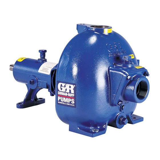
- Page 20 OM−00828 80 SERIES SECTION DRAWING PARTS PAGE Figure 1. Pump Model 82H2−B PAGE E − 2 MAINTENANCE & REPAIR...
- Page 21 OM−00828 80 SERIES PARTS LIST Pump Model 82H2−B (From S/N716064up) If your pump serial number is followed by an N", your pump is NOT a standard production model. Contact the Gorman-Rupp Company to verify part numbers. ITEM PART NAME PART MAT’L ITEM PART NAME...
- Page 22 OM−00828 80 SERIES PUMP AND SEAL DISASSEMBLY 4. Check the temperature before opening any covers, plates, or AND REASSEMBLY plugs. 5. Close the suction and discharge Review all SAFETY information Section A. valves. 6. Vent the pump slowly and cau- Follow the instructions on all tags, label and de- tiously.
- Page 23 80 SERIES OM−00828 Impeller Removal measure and record their thickness for ease of reassembly. Before removing the impeller, turn the cross arm on the automatic grease cup (4) clockwise until it rest Seal Removal and Disassembly against the cover (see Figure 4). This will prevent (Figures 1 or 3) the grease from escaping when the impeller is re- moved.
- Page 24 OM−00828 80 SERIES Remove the setscrews (19) from the bearing re- Clean the bearings thoroughly in fresh cleaning tainer (20) and install two machine screws solvent. Dry the bearings with filtered compressed (#10−32 X 1−inch long, not supplied). Pry the re- air and coat with light oil.
- Page 25 80 SERIES OM−00828 oil and the container must be absolutely clean. If Position the oil seal (21) in the bearing retainer (20) the oil has been previously used, it must be thor- with the lip positioned as shown in Figure 1. Press oughly filtered.
- Page 26 OM−00828 80 SERIES non-oil based solvent and a clean, lint-free tissue. If a replacement seal is being used, remove it from Wipe lightly in a concentric pattern to avoid the container and inspect the precision finished scratching the faces. faces to ensure that they are free of any foreign matter.
- Page 27 80 SERIES OM−00828 the pedestal (12) using two capscrews and nuts Pump Casing Installation (3/8−16 UNC x 1−1/2 inch long, not supplied). If the wear plate (31) was removed, position the re- placement wear plate assembly squarely against Slide the inboard rotating element into the lubri- the casing shoulder and secure it with the mount- cated seal liner with the chamfered side toward the ing hardware (35, 36, 38 and 39).
- Page 28 OM−00828 80 SERIES secure with the nuts (41). Check the operation of Fill the pump casing with clean liquid. Reinstall the the check valve to ensure proper seating and free fill plug (49) and tighten it. movement. Refer to OPERATION, Section C, before putting Final Pump Assembly the pump back into service.
- Page 29 80 SERIES OM−00828 For cold weather operation, consult the factory or a lubricant supplier for the recommended grade of oil. Monitor the condition of the bearing lubri- Power Source cant regularly for evidence of rust or mois- ture condensation. This is especially im- Consult the literature supplied with the power portant in areas where variable hot and source, or contact your local power source repre-...
- Page 30 For U.S. and International Warranty Information, Please Visit www.grpumps.com/warranty or call: U.S.: 419−755−1280 International: +1−419−755−1352 For Canadian Warranty Information, Please Visit www.grcanada.com/warranty or call: 519−631−2870 THE GORMAN-RUPP COMPANY D MANSFIELD, OHIO GORMAN-RUPP OF CANADA LIMITED ST. THOMAS, ONTARIO, CANADA...
Need help?
Do you have a question about the 82H2-B and is the answer not in the manual?
Questions and answers