Table of Contents
Advertisement
Quick Links
ABCDE
COM‐00941‐03
November 18, 2005
INSTALLATION, OPERATION,
AND MAINTENANCE MANUAL
WITH PARTS LIST
80 SERIES PUMP
MODEL
86A52-B
THE GORMAN‐RUPP COMPANY D MANSFIELD, OHIO
www.gormanrupp.com
D
GORMAN‐RUPP OF CANADA LIMITED
ST. THOMAS, ONTARIO, CANADA
Printed in Canada.
e
Copyright by the Gorman‐Rupp Company
Advertisement
Table of Contents

Related Manuals for GORMAN-RUPP PUMPS 86A52-B


Summary of Contents for GORMAN-RUPP PUMPS 86A52-B
- Page 1 COM‐00941‐03 November 18, 2005 INSTALLATION, OPERATION, AND MAINTENANCE MANUAL WITH PARTS LIST 80 SERIES PUMP MODEL 86A52-B THE GORMAN‐RUPP COMPANY D MANSFIELD, OHIO www.gormanrupp.com GORMAN‐RUPP OF CANADA LIMITED ST. THOMAS, ONTARIO, CANADA Printed in Canada. Copyright by the Gorman‐Rupp Company...
-
Page 3: Table Of Contents
TABLE OF CONTENTS INTRODUCTION ..........PAGE I - 1 SAFETY ‐... - Page 4 TABLE OF CONTENTS (continued) TROUBLESHOOTING - SECTION D ......PAGE D - 1 PREVENTIVE MAINTENANCE .
-
Page 5: Introduction
80 SERIES OM-00941 INTRODUCTION Thank You for purchasing a Gorman‐Rupp pump. The following are used to alert maintenance per Read this manual carefully to learn how to safely sonnel to procedures which require special atten install and operate your pump. Failure to do so tion, to those which could damage equipment, and could result in personal injury or damage to the to those which could be dangerous to personnel:... -
Page 7: Safety - Section A
80 SERIES OM-00941 SAFETY ‐ SECTION A This information applies to 80 Series ba 6. Vent the pump slowly and cau sic pumps. Gorman‐Rupp has no con tiously. trol over or particular knowledge of the 7. Drain the pump. power source which will be used. Refer to the manual accompanying the power source before attempting to begin oper... - Page 8 OM-00941 80 SERIES unit and the National Electric Code or other rotating parts. Exposed rotating the applicable local code, the National parts can catch clothing, fingers, or or local code shall take precedence. tools, causing severe injury to person nel. If this pump is used with volatile and/or flammable liquids, overheating may Do not operate the pump against a...
-
Page 9: Installation - Section B
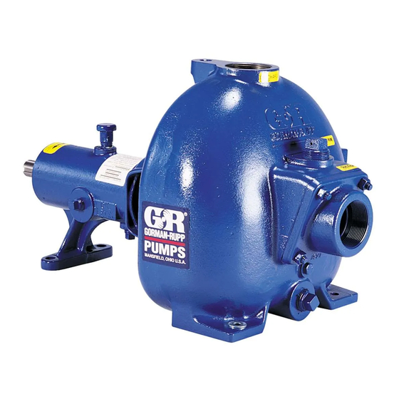
See Figure 1 for the approximate physical dimen configuration, and priming must be tailored to the sions of this pump. OUTLINE DRAWING Figure 1. Pump Model 86A52-B INSTALLATION PAGE B - 1... -
Page 10: Preinstallation Inspection
OM-00941 80 SERIES PREINSTALLATION INSPECTION POSITIONING PUMP The pump assembly was inspected and tested be fore shipment from the factory. Before installation, inspect the pump for damage which may have oc Use lifting and moving equipment in curred during shipment. Check as follows: good repair and with adequate capacity to prevent injuries to personnel or dam... -
Page 11: Line Configuration
80 SERIES OM-00941 compatible with the liquid being pumped. If hose is Fittings used in suction lines, it must be the rigid‐wall, rein Suction lines should be the same size as the pump forced type to prevent collapse under suction. Us inlet. -
Page 12: Suction Line Positioning
OM-00941 80 SERIES suction inlet at a distance 1‐1/2 times the diameter critical to efficient pump operation. Figure 2 shows of the suction pipe. The baffle will allow entrained recommended minimum submergence vs. veloc air to escape from the liquid before it is drawn into ity. -
Page 13: Bypass Lines
80 SERIES OM-00941 É If the application involves a high discharge É É head, gradually close the discharge throttling valve before stopping the pump. Bypass Lines Figure 4. Valve in Closed Position If a system check valve is used due to high dis charge head, it may be necessary to vent trapped air from the top of the pump during the priming When the pump is fully primed, pressure resulting... -
Page 14: Air Release Valve Installation
OM-00941 80 SERIES Air Release Valve Installation NOTE If the Air Release Valve is to be installed on a staged The Automatic Air Release Valve must be inde pump application, position the air release valve as pendently mounted in a horizontal position and close as possible to the discharge check valve. -
Page 15: Coupled Drives
80 SERIES OM-00941 NOTE Check Rotation, Section C, before final alignment of the pump. When mounted at the Gorman‐Rupp factory, driver and pump are aligned before shipment. Misalign ment will occur in transit and handling. Pumps must be checked and realigned before operation. Before checking alignment, tighten the foundation bolts. -
Page 16: Drive Belt Tensioning
OM-00941 80 SERIES DRIVE BELT TENSIONING General Rules of Tensioning For new drive belts, check the tension after 5, 20 and 50 hours of operation and re‐tension as re quired (see the following procedure for measuring belt tension). Thereafter, check and re‐tension if re quired monthly or at 500 hour intervals, whichever comes first. -
Page 17: Operation - Section C
OM-00941 80 SERIES OPERATION - SECTION C Review all SAFETY information in Section A. PRIMING Follow the instructions on all tags, labels and Install the pump and piping as described in IN decals attached to the pump. STALLATION. Make sure that the piping connec tions are tight, and that the pump is securely mounted. -
Page 18: Starting
OM-00941 80 SERIES STARTING OPERATION Lines With a Bypass Consult the operations manual furnished with the power source. Close the discharge throttling valve (if so equipped) so that the pump will not have to prime If the pump has been approved for use with petro against the weight of the liquid in the discharge line. -
Page 19: Strainer Check
OM-00941 80 SERIES boil, build pressure, and cause the pump to rup lift, and should then stabilize. If the vacuum reading ture or explode. If overheating occurs, stop the falls off rapidly after stabilization, an air leak exists. pump and allow it to completely cool before servic Before checking for the source of the leak, check the point of installation of the vacuum gauge. - Page 20 OM-00941 80 SERIES curately by placing a contact‐type thermometer rect level (see LUBRICATION in Section E). Bear against the housing. Record this temperature for ing overheating can also be caused by shaft future reference. misalignment and/or excessive vibration. A sudden increase in bearing temperatures is a When pumps are first started, the bearings may warning that the bearings are at the point of failing seem to run at temperatures above normal.
- Page 21 80 SERIES OM-00941 TROUBLESHOOTING - SECTION D Review all SAFETY information in Section A. Before attempting to open or service the pump: 1. Familiarize yourself with this man ual. 2. Lock out or disconnect the power source to ensure that the pump will remain inoperative.
- Page 22 OM-00941 80 SERIES TROUBLE POSSIBLE CAUSE PROBABLE REMEDY Impeller or other wearing parts worn Replace worn or damaged parts. PUMP STOPS OR FAILS TO DELIVER or damaged. Check that impeller is properly RATED FLOW OR centered and rotates freely. PRESSURE (cont.) Impeller clogged.
- Page 23 80 SERIES OM-00941 equipped) between regularly scheduled inspec PREVENTIVE MAINTENANCE tions can indicate problems that can be corrected Since pump applications are seldom identical, and before system damage or catastrophic failure oc pump wear is directly affected by such things as curs.
- Page 25 PUMP MAINTENANCE AND REPAIR - SECTION E MAINTENANCE AND REPAIR OF THE WEARING PARTS OF THE PUMP WILL MAINTAIN PEAK OPERATING PERFORMANCE. STANDARD PERFORMANCE FOR PUMP MODEL 86A52-B Based on 70_ F (21_ C) clear water at sea level Contact the Gorman‐Rupp Company to verify per...
- Page 26 OM-00941 80 SERIES SECTION DRAWING PARTS PAGE Figure 1. Pump Model 86A52-B PAGE E - 2 MAINTENANCE & REPAIR...
- Page 27 OM-00941 80 SERIES PARTS LIST Pump Model 86A52-B (From S/N 1329204 up) If your pump serial number is followed by an “N”, your pump is NOT a standard production model. Contact the Gorman‐Rupp Company to verify part numbers. ITEM PART NAME...
- Page 28 OM-00941 80 SERIES PUMP AND SEAL DISASSEMBLY 4. Check the temperature before opening any covers, plates, or AND REASSEMBLY plugs. 5. Close the suction and discharge Review all SAFETY information in Section A. valves. 6. Vent the pump slowly and cau Follow the instructions on all tags, label and de...
- Page 29 80 SERIES OM-00941 Pump Casing Removal Turn Counterclockwise To service the impeller (2), wear plate (44) and seal assembly (3), disconnect the discharge piping. Remove the hardware securing the pump casing Lathe Dog Arm (1) to the base. “V” Notch Remove the nuts (40) securing the pump casing Heavy Shaft Key...
- Page 30 OM-00941 80 SERIES If no further disassembly is required, see Seal Place a block of wood against the drive end of the Reassembly and Installation. shaft and tap the shaft and assembled bearings (19 and 23) out of the pedestal. After removing the shaft and bearings, clean and Shaft And Bearing Removal And Disassembly inspect the bearings in place as follows.
- Page 31 80 SERIES OM-00941 tation is rough or the bearing balls are discolored, replace the bearings. The bearing tolerances provide a tight press fit Use caution when handling hot bear onto the shaft and a snug slip fit into the pedestal. ings to prevent burns.
- Page 32 OM-00941 80 SERIES bearing retainer O‐ring (32) in the pedestal, and lu precautions printed on solvent contain bricate it with grease. ers. The seal is not normally reused because wear pat Slide the the assembled bearing retainer and oil terns on the finished faces cannot be realigned seal over the shaft and press it into the pedestal un...
- Page 33 80 SERIES OM-00941 ROTATING ELEMENT O‐RING STATIONARY SEAT SPRING IMPELLER IMPELLER IMPELLER SHAFT ADJUSTING SHIMS SHAFT SLEEVE SPRING SEAL SEAT PLATE RETAINER BELLOWS Figure 3. 25284-961 Seal Assembly until the face of the rotating element is just flush with the chamfered end of the sleeve. Slide the assembled seal and sleeve onto the shaft This seal is not designed for operation at until the seal faces contact.
- Page 34 OM-00941 80 SERIES After the back clearance is set, secure the impeller Final Pump Assembly with the hardware (41, 42 and 43). Be sure the pump and power source are securely Pump Casing Installation mounted to the base. Reconnect the power source to the pump.
- Page 35 80 SERIES OM-00941 For cold weather operation, consult the factory or a lubricant supplier for the recommended grade of oil. Monitor the condition of the bearing lubri Power Source cant regularly for evidence of rust or mois ture condensation. This is especially im Consult the literature supplied with the power portant in areas where variable hot and source, or contact your local power source repre...
- Page 38 For Warranty Information, Please Visit www.grpumps.com/warranty or call: U.S.: 419-755-1280 Canada: 519-631-2870 International: +1-419-755-1352 GORMAN‐RUPP PUMPS...
Need help?
Do you have a question about the 86A52-B and is the answer not in the manual?
Questions and answers