GORMAN-RUPP PUMPS 80 Series Installation, Operation And Maintenance Manual
Hide thumbs
Also See for 80 Series:
Table of Contents
Advertisement
Quick Links
OM-00832-02
ACE
January 8, 1980
Rev. E 03-14-05
INSTALLATION, OPERATION,
AND MAINTENANCE MANUAL
WITH PARTS LIST
80 SERIES PUMPS
MODEL
82H4−B
THE GORMAN-RUPP COMPANY D MANSFIELD, OHIO
D
GORMAN-RUPP OF CANADA LIMITED
ST. THOMAS, ONTARIO, CANADA
Printed in U.S.A.
www.gormanrupp.com
e
Copyright by the Gorman-Rupp Company
Advertisement
Table of Contents

Related Manuals for GORMAN-RUPP PUMPS 80 Series


Summary of Contents for GORMAN-RUPP PUMPS 80 Series
- Page 1 OM-00832-02 January 8, 1980 Rev. E 03-14-05 INSTALLATION, OPERATION, AND MAINTENANCE MANUAL WITH PARTS LIST 80 SERIES PUMPS MODEL 82H4−B THE GORMAN-RUPP COMPANY D MANSFIELD, OHIO GORMAN-RUPP OF CANADA LIMITED ST. THOMAS, ONTARIO, CANADA Printed in U.S.A. www.gormanrupp.com Copyright by the Gorman-Rupp Company...
-
Page 2: Table Of Contents
TABLE OF CONTENTS INTRODUCTION ..........PAGE I −... - Page 3 TABLE OF CONTENTS (continued) TROUBLESHOOTING − SECTION D ......PAGE D − 1 PREVENTIVE MAINTENANCE .
-
Page 4: Introduction
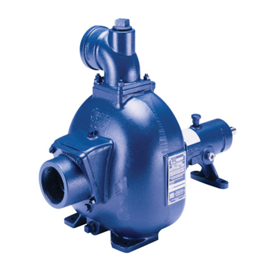
Gorman- Rupp pump. This pump is an 80 Series, semi-open impeller, self- priming centrifugal model with a suction check valve. The pump is designed for handling liquids Immediate hazards which WILL result in containing specified entrained solids. -
Page 5: Safety - Section A
80 SERIES OM−00832 SAFETY - SECTION A This information applies to 10 Series ba- sic pumps. Gorman-Rupp has no con- trol over or particular knowledge of the power source which will be used. Refer This pump is designed to handle liquids to the manual accompanying the power containing specified entrained solids. - Page 6 OM−00832 80 SERIES Do not operate the pump against a Overheated pumps can cause severe closed discharge valve for long periods burns and injuries. If overheating of the of time. If operated against a closed dis- charge valve, pump components will...
-
Page 7: Installation − Section Bpage B
80 SERIES OM−00832 INSTALLATION − SECTION B Review all SAFETY information in Section A. specific application. Since the pressure supplied to the pump is critical to performance and safety, Since pump installations are seldom identical, this be sure to limit the incoming pressure to 50% of the... -
Page 8: Preinstallation Inspection Page B
OM−00832 80 SERIES PREINSTALLATION INSPECTION POSITIONING PUMP The pump assembly was inspected and tested be- fore shipment from the factory. Before installation, inspect the pump for damage which may have oc- Use lifting and moving equipment in curred during shipment. Check as follows: good repair and with adequate capacity a. -
Page 9: Line Configuration
80 SERIES OM−00832 compatible with the liquid being pumped. If hose is Fittings used in suction lines, it must be the rigid-wall, rein- Suction lines should be the same size as the pump forced type to prevent collapse under suction. Us- inlet. -
Page 10: Suction Line Positioning
OM−00832 80 SERIES If it is necessary to position inflow close to the suc- Suction Line Positioning tion inlet, install a baffle between the inflow and the The depth of submergence of the suction line is suction inlet at a distance 1-1/2 times the diameter critical to efficient pump operation. -
Page 11: Bypass Lines
80 SERIES OM−00832 With high discharge heads, it is recommended that Bypass Lines a throttling valve and a system check valve be in- Self-priming pumps are not air compressors. Dur- stalled in the discharge line to protect the pump ing the priming cycle, air from the suction line must from excessive shock pressure and reverse rota- be vented to atmosphere on the discharge side. - Page 12 OM−00832 80 SERIES NOTE The bypass line should be sized so that it does not affect pump discharge capacity; however, the by- pass line should be at least 1 inch (25,4 mm) in di- ameter to minimize the chance of plugging.
-
Page 13: Automatic Air Release Valve
80 SERIES OM−00832 bypass of liquid to 1 to 5 gallons per minute, until AUTOMATIC AIR RELEASE VALVE the pump loses its prime or stops. When properly installed and correctly adjusted to the specific hydraulic operating conditions of the application, the Gorman-Rupp Automatic Air Re-... -
Page 14: Alignment
OM−00832 80 SERIES DISCHARGE PIPE CLEAN-OUT COVER INSTALL AIR RELEASE VALVE IN HORIZONTAL POSITION DISCHARGE CHECK VALVE 90_ LONG RADIUS ELBOW SUPPORT PUMP DISCHARGE BRACKET SELF-PRIMING CENTRIFUGAL PUMP BLEED LINE 1" (25,4 MM) DIA. MIN. (CUSTOMER FURNISHED) EXTEND 6" SUCTION... -
Page 15: Coupled Drives
80 SERIES OM−00832 When checking alignment, disconnect the power source to ensure that the pump will remain inoperative. Adjusting the alignment in one direction may alter the alignment in another direc- Figure B−7. Alignment of V-Belt Driven tion. Check each procedure after altering Pumps alignment. - Page 16 OM−00832 80 SERIES Tighten the belts in accordance with the belt manu- facturer’s instructions. If the belts are too loose, they will slip; if the belts are too tight, there will be excessive power loss and possible bearing failure. Do not operate the pump without the...
-
Page 17: Operation − Section C
OM−00832 80 SERIES OPERATION − SECTION C Review all SAFETY information in Section A. Add liquid to the pump casing when: 1. The pump is being put into service for the Follow the instructions on all tags, labels and first time. -
Page 18: Operation
OM−00832 80 SERIES Consult the operating manual furnished with the Leakage pump power source before attempting to start the No leakage should be visible at pump mating sur- power source. faces, or at pump connections or fittings. Keep all line connections and fittings tight to maintain maxi- If an electric motor is used to drive the pump, re- mum pump efficiency. -
Page 19: Stopping
OM−00832 80 SERIES Block the suction line and start the pump. At oper- for approximately one minute; this will remove any ating speed the pump should pull a vacuum of 20 remaining liquid that could freeze the pump rotat- inches (508,0 mm) or more of mercury. If it does ing parts. - Page 20 80 SERIES OM−00832 TROUBLESHOOTING − SECTION D Review all SAFETY information in Section A. Before attempting to open or service the pump: 1. Familiarize yourself with this manual. 2. Disconnect or lock out the power source to ensure that the pump will remain inoperative.
- Page 21 OM−00832 80 SERIES TROUBLE POSSIBLE CAUSE PROBABLE REMEDY PUMP STOPS OR Leaking or worn seal or pump gasket. Check pump vacuum. Replace FAILS TO DELIVER leaking or worn seal or gasket. RATED FLOW OR Impeller clogged. Free impeller of debris.
- Page 22 80 SERIES OM−00832 equipped) between regularly scheduled inspec- PREVENTIVE MAINTENANCE tions can indicate problems that can be corrected Since pump applications are seldom identical, and before system damage or catastrophic failure oc- pump wear is directly affected by such things as curs.
- Page 23 80 SERIES OM−00832 PUMP MAINTENANCE AND REPAIR - SECTION E MAINTENANCE AND REPAIR OF THE WEARING PARTS OF THE PUMP WILL MAINTAIN PEAK OPERATING PERFORMANCE. STANDARD PERFORMANCE FOR PUMP MODEL 82H4−B Based on 70_ F (21_ C) clear water at sea level Contact the Gorman-Rupp Company to verify per- formance or part numbers.
- Page 24 OM−00832 80 SERIES SECTION DRAWING PARTS PAGE Figure 1. Pump Model 82H4−B PAGE E − 2 MAINTENANCE & REPAIR...
- Page 25 80 SERIES OM−00832 PARTS LIST Pump Model 82H4−B (From S/N 710557 up) If your pump serial number is followed by an N", your pump is NOT a standard production model. Contact the Gorman-Rupp Company to verify part numbers. ITEM PART NAME PART MAT’L...
- Page 26 OM−00832 80 SERIES PUMP AND PACKING DISASSEMBLY 4. Check the temperature before opening any covers, plates, or AND REASSEMBLY plugs. 5. Close the suction and discharge Review all SAFETY information in Section A. valves. 6. Vent the pump slowly and cau- Follow the instructions on all tags, label and de- tiously.
- Page 27 OM−00832 80 SERIES pacity to separate the casing from the seal plate Turn and pedestal. Counterclockwise Lathe Dog Arm Do not attempt to lift the complete pump unit using the lifting eye. It is designed to facilitate removal or installation of in- V"...
- Page 28 OM−00832 80 SERIES Inspect the spacer sleeve (8) for nicks or scratches. Dress small nicks and burrs with a fine file or emery cloth. If necessary, replace the sleeve. To prevent damage during removal from If no further disassembly is required, see Packing the shaft, it is recommended that bearings Installation.
- Page 29 OM−00832 80 SERIES Press the inboard oil seal (28) from the pedestal not moved away from the shaft shoulders in shrink- bore. ing. If movement has occurred, use a suitably sized sleeve and a press to reposition the bearings against the shaft shoulders.
- Page 30 OM−00832 80 SERIES 0,12 mm). Add or remove bearing adjusting shims to obtain this endplay. Install the slinger ring (11) on the shaft. Lubricate the pedestal as indicated in LUBRICA- TION at the end of this section. Seal Reassembly and Installation...
- Page 31 OM−00832 80 SERIES mended by the packing manufacturer. In general, swabbing the inside diameter of of type packing with SAE No. 30 non-deter- gent oil provides sufficient lubrication. Step 3: Lubricate all metallic packings (foil type, lead core, etc.) with the lubricant recom-...
- Page 32 OM−00832 80 SERIES Install the packing gland set into the seal plate and plate and pedestal with the nuts (33). Do not fully secure each half with the mounting hardware (30 tighten the nuts at this time. and 31) and gland clips (29). Draw up the deform A clearance of .010 to .020 inch (0,25 to 0,51 mm)
- Page 33 OM−00832 80 SERIES Be sure the pump and power source are securely through the auxiliary lubrication piping provided in mounted to the base. the seal plate. Be sure liquid supplied to the seal is compatible with the liquid being pumped, and that Install the suction and discharge lines and open all its flow is controlled to prevent dilution.
- Page 34 For U.S. and International Warranty Information, Please Visit www.grpumps.com/warranty or call: U.S.: 419−755−1280 International: +1−419−755−1352 For Canadian Warranty Information, Please Visit www.grcanada.com/warranty or call: 519−631−2870 THE GORMAN-RUPP COMPANY D MANSFIELD, OHIO GORMAN-RUPP OF CANADA LIMITED ST. THOMAS, ONTARIO, CANADA...
Need help?
Do you have a question about the 80 Series and is the answer not in the manual?
Questions and answers