Table of Contents
Advertisement
Advertisement
Table of Contents

Subscribe to Our Youtube Channel
Related Manuals for OLIMEX AgonLight2


Summary of Contents for OLIMEX AgonLight2
- Page 1 AgonLight2 User Manual Rev.1.1 January 2023...
-
Page 2: Table Of Contents
Table of Contents Introduction..............................3 What is AgonLight2?..........................4 AgonLight references documents:......................5 The difference between AgonLight and AgonLight2:................6 Order codes for AgonLight2 and accessories:..................7 HARDWARE.............................8 AgonLight2 layout:..........................9 AgonLight2 schematic:........................10 AgonLight2 power supply and consumption:..................15 GPIO connector:..........................16 UEXT connector:..........................18 Access bus connector:.........................19 eZ80 programming connector:......................20... -
Page 3: Introduction
Introduction... -
Page 4: What Is Agonlight2
What is AgonLight2? AgonLight2 is re-design of the original AgonLight eZ80F92 retro computer, designed as hobby project by Bernardo Kastrup. AgonLight2 is complete Single Board Computer with VGA display output, PS2 keyboard and SD card (acting as external Disk), so to write programs and run them you do not need external computer like Arduino does. -
Page 5: Agonlight References Documents
AgonLight references documents: Here we link original AgonLight Hardware Manual, QuickStart Guide Firmware Installation Guide. Note that AgonLight2 will come to you completely assembled, tested and with programmed firmware, so you can use the above documents just for reference and completeness. -
Page 6: The Difference Between Agonlight And Agonlight2
Fixed GPIO and Programming connector pin ordering; • Replaced the nacked header 32-pin connector with a plastic boxed 34-pin connector following the same layout and adding two additional signals Vbat and Vin which allow AgonLight2 to be powered by this connector too. •... -
Page 7: Order Codes For Agonlight2 And Accessories
Order codes for AgonLight2 and accessories: AgonLight2 - Single Board BBC Basic Z80 Retro style Computer AgonLight2-BOX - Metal box for AgonLight2 CABLE-USB-A-C-1M - USB-C power cable BATTERY-LIPO1400mAh - Lipo battery 3.7V 1400mAh – note these batteries can be shipped only by ground so we can deliver only to EU destinations. -
Page 8: Hardware
HARDWARE... -
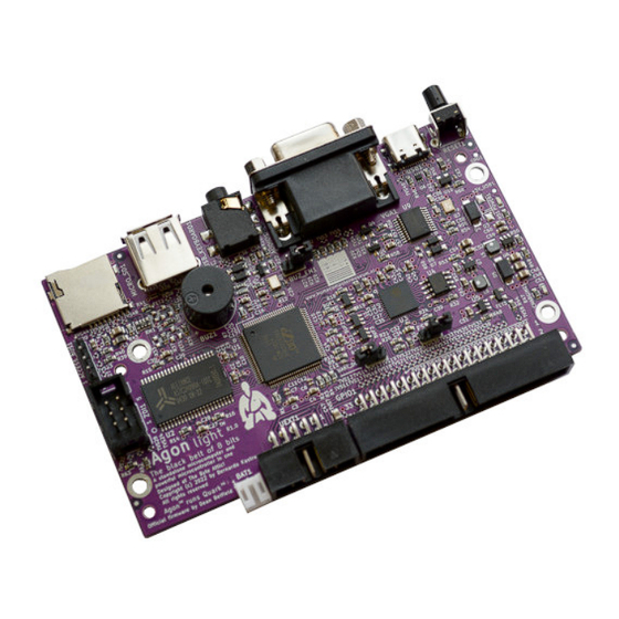
Page 9: Agonlight2 Layout
AgonLight2 layout: Buzzer Reset USB-C Power Audio Out Micro SD card USB-PS2 keyboard Buzzer enable Access bus ESP32 UART disable EZ80 programming ESP32 programming LiPo battery UEXT GPIO... -
Page 10: Agonlight2 Schematic
AgonLight2 schematic: The current AgonLight2 schemaitc is available for download and print on GuitHub... -
Page 15: Agonlight2 Power Supply And Consumption
8 hours of stand alone operation. The LiPo battery connector is JST 2.0 mm connector and with Olimex’s battery polarity. If you use batteries from other manufacturers please make PLUS and MINUS are connected properly as you... -
Page 16: Gpio Connector
GPIO connector: Pin.1 is connected to the LiPo battery PLUS you can connect external battery on this pin or to use battery voltage to external circuits. Pin. 2 is 5V power supply connected to USB-C +5V signal, you can power the board from this signal if the USB-C is not connected. - Page 17 Pin.34 is +3.3V output capable to source up to 2A note that 200mA are used by AgonLight2 Pin.4 is +5V output capable to source up to 2A (1.8A + AgonLight2 0.2A), it’s backed by LiPo UPS so even if there is interruption on power supply if LiPo battery is attached there will be 5V on this pin.
-
Page 18: Uext Connector
UEXT connector stands for Universal EXTension connector and contain +3.3V, GND, I2C, SPI, UART signals: UEXT is 0.1” 2.54mm step boxed plastic connector. All signals are with 3.3V levels. Olimex has developed number of MODULES with this connector. There are temperature, humidity, pressure, magnetic field, light sensors. -
Page 19: Access Bus Connector
Access bus connector: This is I2C and power supply with 3.3V levels. -
Page 20: Ez80 Programming Connector
This connector is used for initial programming of eZ80 microcontroller. AgonLight2 comes with pre- programmed firmware so you do not need to use this connector nor programmer for it. If you want to develop your own firmware... -
Page 21: Jumpers
Jumpers: Buzzer enable jumper – when closed the buzzer plays the sound commands. ESP programming enable when closed ESP32 enters bootloader mode at Reset and can be programmed over the USB-C connector UART disable – when closed the UART connection between eZ80 and ESP32 is disconnected. -
Page 22: Software
SOFTWARE:... -
Page 23: Agonlight2 Firmware
9. Insert the uSD card into the board. 10. Connect a VGA monitor and a PS/2 keyboard (or a PS/2-compatible USB keyboard, via a PS/2 adapter) to the AgonLight2 unit. 11. Turn the AgonLight2 board on my connecting it to power via the USB cable:... -
Page 24: Mos Commands
MOS commands: LOAD “” SAVE “” *CAT *DIR *CD / *MKDIR *BYE *CPM *ERA file *ESC [ON OFF] *EXEC file *OPT *REN oldfile ewfile *SAVE file aaaa bbbb *SPOOL file *TYPE file *| comment... -
Page 25: Bbc Basic Commands Reference
BBC Basic commands reference: Variables: X – float X% - integer X$ - string &X - hex Pressing ESC key breaks the code execution This is list of the BBC Basic commands click on the command name for more info and use. LOMEM REPORT MID$... -
Page 26: Software Access To Gpios
Software access to GPIOs: eZ80 ports are described in the eZ80-specification. Port direction register set if the port is INPUT or OUTPUT. Upon RESET all GPIOs are set as Inputs. Direction registers are 8 bit and each bit corresponds to port signal. If 1 is written on the corresponding port will be set as Input if 0 as Output. -
Page 27: Software Access To I2C
Software access to I2C:... -
Page 28: Software Access To Spi
Software access to SPI:... -
Page 29: Software Access To Vpu
Software access to VPU:... -
Page 30: Revision History
Revision History Revision 1.0 January 2023 - initial release Revision 1.1 January 2023 - added “How to prepare the SD card and boot the first time”, taken and edited from “Agon light™ Firmware Installation Guide.pdf”...
Need help?
Do you have a question about the AgonLight2 and is the answer not in the manual?
Questions and answers