
Related Manuals for OLIMEX SAM3-P256


Summary of Contents for OLIMEX SAM3-P256
- Page 1 SAM3-P256 development board user's manual All boards produced by Olimex are ROHS compliant Rev. C, September 2014 Copyright(c) 2011, OLIMEX Ltd, All rights reserved Page 1...
-
Page 2: Board Features
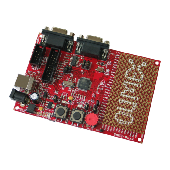
16-bit timers, an RTC, an ADC, a 12-bit DAC and an analog com- parator. SAM3-P256 has JTAG, UEXT, USB and two RS232 connectors, power jack, potentiometer, two user buttons, two status LEDs, power-on led, reset button and prototype area for all microcontroller's ports. All this gives the customer chance to build a wide range of applications. -
Page 3: Electrostatic Warning
BOARD USE REQUIREMENTS: Cables: The cable you will need depends on the programmer/debugger you use. OLIMEX debuggers need USB type B to USB type A cable to connect to a computer. Hardware: The best idea is to use a debugger made by Atmel, since the main microcontroller is made by Atmel. - Page 4 Power-on-Reset (POR), Brown-out Detector (BOD) and Watchdog for safe operation Quartz or ceramic resonator oscillators: 3 to 20 MHz main power with Failure Detection and optional low power 32.768 kHz for RTC or device clock High precision 8/12 MHz factory trimmed internal RC oscillator with 4 ...
- Page 5 47 I/O lines with external interrupt capability (edge or level sensitivity), debouncing, glitch filtering and on-die Series Resistor Termination Three 32-bit Parallel Input/Output Controllers, Peripheral DMA assisted Parallel Capture Mode Page 5...
-
Page 6: Block Diagram
BLOCK DIAGRAM: Page 6... -
Page 7: Memory Map
MEMORY MAP: Page 7... - Page 8 PB1/PWMH1/AD5 GND2 PB2/URXD1/NPCS2/WKUP12/AD6 FET2 TERMISTOR GND3 PB3/UTXD1/PCK2/AD7 (NA)IRLML6402 100n GND4 2.2uF 100n 100n 100n NA(1.5K) ATSAM3S4BA-AU NA(47K) 3.3V 3.3V 3.3V DP_PUP NA(100) UEXT 4.7K 4.7K Made by Olimex LTD, Bulgaria, 2013 TXD1 RXD1 TWCK MISO MOSI https://www.olimex.com SPCK NPCS1 BH10S...
-
Page 9: Board Layout
BOARD LAYOUT: Page 9... -
Page 10: Reset Circuit
POWER SUPPLY CIRCUIT: SAM3-P256 is typically power supplied with 6 VDC via Power jack, but it can be also power supplied via USB with +5V. The programmed board power consumption is about 100 mA with all peripherals enabled. RESET CIRCUIT: SAM3-P256 reset circuit includes U2 (MCP130T), R22 (10k), pin 15 of JTAG connector, ATSAM3S4BA-AU pin 39 (NRST) and RESET button. - Page 11 VREF_P: This jumper, when is closed, ATSAM3S4BA-AU pin1 (ADVREF) is connected to VCC (3.3V). When this jumper is opened, ATSAM3S4BA-AU pin1 (ADVREF) is connected to VREF pin. Default state is closed. RXD0/DRXD: This jumper, when is in position RXD0, R0OUT is connected to ATSAM3S4BA-AU pin 35 (PA5/RXD0), i.e.
- Page 12 Description for programming via RS232_0/D COM port, or USB port using SAM-BA software: Using SAM-BA software ATSAM3S4BA-AU can be programmed via COM port (with external power supply only), or via USB port (with USB power supply only). Before being able to use SAM-BA, a recovery procedure, which consists of copying the SAM-BA Boot Assistant into Flash must be performed as follows: 1.Power down the ATSAM3S4BA-AU...
-
Page 13: External Connectors Description
EXTERNAL CONNECTORS DESCRIPTION: RS232_0/D: Pin # Signal Name TX0OUT RX0IN RS232_1: Pin # Signal Name TX1OUT RX1IN Page 13... - Page 14 PWR: Pin # Signal Name Power Input UEXT: Pin # Signal Name TXD1 RXD1 TWCK MISO MOSI SPCK NPCS1 JTAG: The JTAG connector allows the software debugger to talk via a JTAG (Joint Test Action Group) port directly to the core. Instructions may be inserted and executed by the core thus allowing ATSAM3S4BA-AU memory to be programmed with code and executed step by step by the host software.
- Page 15 Pin # Signal Name Pin # Signal Name TRST RTCK USB: Pin # Signal Name +5V_USB Page 15...
- Page 16 SD/MMC: Pin # Signal Name Pin # Signal Name NPCS0 MOSI GND (VSS1) SPCK GND (VSS2) MISO Via R31 (47k) to 3.3V Via R34 (47k) to 3.3V Via R26 (2k) to GND Via R38 (2k) to GND Via R26 (2k) to GND Via R38 (2k) to GND Page 16...
- Page 17 Prototype area: NC – Not connected. Page 17...
-
Page 18: Mechanical Dimensions
MECHANICAL DIMENSIONS: Page 18... - Page 19 AVAILABLE DEMO SOFTWARE: The demo package available at the Software section of SAM3-P256's page features the following examples: Getting started – demonstrates use of LEDs, User buttons, Interrupts and Timers ADC demo – demonstrates use of analog peripherals on board ...
-
Page 20: Order Code
SAM3-P256 – assembled and tested board How to order? You can order directly from our web ship or purchase from any of our distributors. The list of Olimex distributors might be found here: https://www.olimex.com/Distributors Check our web site https://www.olimex.com/ for more info. - Page 21 This document is intended only to assist the reader in the use of the product. OLIMEX Ltd. shall not be liable for any loss or damage arising from the use of any information in this document or any error or omission in such information or any incorrect use of the product.
Need help?
Do you have a question about the SAM3-P256 and is the answer not in the manual?
Questions and answers