
Related Manuals for OLIMEX DuinoMite


Summary of Contents for OLIMEX DuinoMite
- Page 1 DuinoMite User's Manual Revision 1.03 December 2011 Copyright 2011, Olimex Ltd (Based on original Maximite by Geoff Graham www.geoffg.net) Released under Creative Commons Attribution Share Alike 3.0 United States Licensee...
- Page 2 , which generally means that you are free to use these files Attribution-Share Alike 3.0 United States License to create your own product providing you credit Olimex as the source and release your files with the same license as well.
- Page 3 This is, to date, the most sophisticated board from DuinoMite range of boards. The schematic of the current revision of the DuinoMite-Mega can be found online in the DUINO section at http://www.olimex.com/dev, you will also find the CAD schematics and board files.
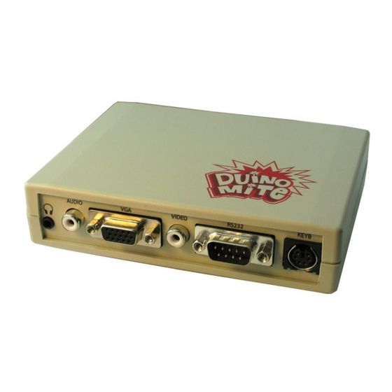
- Page 4 DuinoMite-Mega is available for sale as either a pre-assembled board only or alternatively, in a laser cut, custom made plastic enclosure:...
- Page 5 Hardware features: – PIC32MX795F512H processor running at with RAM and Flash 80Mhz 128KB 512KB – DC-DC power supply DC input 9-30V – USB / USB Device Host OTG – mini socket SD card – two connectors, one inside enclosure, one outside UEXT connector –...
- Page 6 – Linear power regulator, require to the DC POWER JACK EXACTLY 5V – USB DuinoMite-Mini can take power from USB also, there is 3 way jumper Device which selects which source is used the DC POWER JACK or the USB – mini...
- Page 7 This is a compact, low cost board in ARDUINO form factor ready to interface with ARDUINO shields. The schematic of the current revision of DuinoMite, DuinoMite-IO, DuinoMite-Shield is at http://www.olimex.com/dev in DUINO section, where you will also find the CAD schematics and board files.
- Page 8 DuinoMite-Mega, but with some additional features such as Ethernet connector and PHY controller, which will add a 100Mbit Ethernet interface to DuinoMite, 2MB on board Data Flash which could be used as disk for data and code storage. PMP external connector with 80Mhz clock which could be used to interface to TFT displays, fast ADCs, allowing Duinomite to be used as Logic Analyzer, Digital Storage oscilloscope, capture for fast external signals.
- Page 9 2.3. PIC32-T795 (breadboarding PIC32MX795) This is a new breadboard based on Ken Segler's design. It is T-shaped and is intended to plug into a breadboard. It incorporates a UEXT connector and USB with Device and Host (OTG) PIC32-T795 is the fastest way to make something with a breadboard and Jumper wires without the need to solder.
-
Page 10: Power Supply
- USB power supply, when DuinoMite-Mega is connected via a USB cable to a USB host it will take its 5V power supply from the USB host source to power the board, note that depending on what... - Page 11 9VDC). 3.1.2. DuinoMite-Mini The DuinoMite-Mini power supply is made with a linear voltage regulator to save cost (an LM1117 is used). The power source could be USB connector or POWER JACK. The source is selected with a 3- way jumper. The board has a protection ZENER diode (6.8V) on the input to protect the board from over-voltage spikes on the power supply.
- Page 12 Of course all of these devices need proper drivers to be implemented. This mode is not yet supported by DuinoMite-Mini board. Special care is taken in the DuinoMite design for USB noise immunity and protection when it works in host mode.
- Page 13 The uSD power supply is designed with ferrite bead filtering to minimise noise problems. As DuinoMite, and DuinoMite-Mega are designed to be low power boards there is provision for the SD-card power supply to be shut down, this is done with FET2 connected to STB_E on RB13 port of PIC32.
- Page 14 By having these signals available on a fixed interface allows us to develop different modules which can be used on any board with a UEXT connector. All DuinoMite boards have UEXT connectors and can interface Olimex's UEXT modules. For more information on UEXT see: http://www.olimex.com/dev/OTHER/UEXT.pdf...
- Page 15 D0 – D13 are digital I/Os, A0-A5 are analog I/Os, VIN – input power which allows you to power DuinoMite (or Mega) by an external power supply RST – reset CTS, RTS – handshake signals from the Mega's RS232 connector, they are TTL levels.
- Page 16 NOTES! D0 & D1 are wired via protection resistors to the RS232 connector (COM4) on the DuinoMite-Mega this means that if there are signals on the RS232 connector they will affect D0, if D1 is initialized as INPUT this signal will merge with the signal on ARDUINO.D0 connector. Also if D1 is initialized as output it will affect COM4 port transmission.
- Page 17 CAN is available only on the DuinoMite-Mega. CAN is a very useful interface, it’s the de-facto standard for automotive bus applications, so by having CAN it would be possible to connect to your car and read all of the data sensors for speed, temperatures, fuel consumption, etc.
- Page 18 3.7. GPIO The original MaxiMite introduced the 26 pin GPIO connector. With the emergence of the DuinoMite and support for ARDUINO we expanded the GPIO layout as shown below: MM-BASIC allows the GPIO ports to be accessed with the PIN() command and function, and different functions to be set with SETPIN command.
- Page 19 - period input PI - counter input CI - interrupt low-to-high IP - interrupt high-to-low IN - digital output DO - digital output open collector OC MMBasic Arduino 26pin header Allowable SETPIN Referrence: Referrence Pin No. Configurations PIN(1) → ARDUINO.A0 AI, DI, , , IP, IN, DO, PIN(2) →...
- Page 20 3.8. PS-2 KEYBOARD PS2 keyboard CLOCK is connected to RD6 and DATA is connected to RD7. Note that the Keyboard requires 5V to work correctly, so the keyboard will not work when the DuinoMite-Mega is powered by 3.7V LiPo battery.
- Page 21 3.9. VGA / Video The VGA monitor is uses the PIC32 SPI to generate the video signal. VGA.HSYNC is generated by RD4, VGA.VSYNC is generated by RB12 which is also connected to LED2 (YELLOW) and ARDUINO.D9. VGA R/G/B signals are connected together via small SMD jumpers if you selectively cut them you can make your Video output RED, GREEN, BLUE, AMBER or YELLOW in color.
- Page 22 3.10. AUDIO The DuinoMite has two connectors, an AUDIO RCA jack connector and a 3.5mm headphone connector. MM-BASIC can output to these connectors with the SOUND command, with frequencies up to 1Mhz, and by using the duty cycle parameter, PWM will be available from these connectors.
- Page 23 3.11. LEDS The DuinoMite has three LEDs: –RED power supply LED, is ON when the board is powered by external power supply or USB, and is OFF if the power supply is the LiPo battery. –YELLOW is the system RUN status, if this LED is ON, VGA video is generated correctly and the board is ready to work.
- Page 24 RESET button does a hardware reset (hot start) and all code in memory is cleared and board initialized as if it was just powered up. The Duinomite has a boot-loader which allows the firmware to be upgraded without need of an external programmer. To enter the boot-loader the USER button should be pressed at power-up or RESET.
- Page 25 3.13. BATTERY The DuinoMite and DuinoMite-Mega have a built-in LiPo battery charger and the hardware is designed to allow them to run in low power mode for battery operation. USB-FAULT is connected to RG7 to allow the firmware to be aware that it is running on battery instead of an external power supply.
- Page 26 3.14. HARDWARE SIGNATURE The DuinoMite hardware signature allows the firmware to be aware of which board it is running. This is very useful for the boot-loader to determine which firmware to download to it. The signature is done by a voltage divider made from R40/R30 read on RB14 initialized as analog input. For the current revision of the hardware the voltage divider is 1:10 so if 0.33V is read on this port your code runs on...
- Page 27 4. SOFTWARE...
- Page 28 Microchip programmer as DuinoMite uses a small 0.05” ICSP connector instead of the more common 0.10" ICSP connector. With this setup you have access to a complete development environment which works on Windows, Linux, MAC OS and you can use all of the hardware features of DuinoMite boards.
- Page 29 Pinguino programming environment, the only difference is that a different boot-loader should be programmed into the DuinoMite to support Pinguino IDE. The Pinguino IDE allows you to program the DuinoMite in ARDUINO language or pure C/C++ and load the code with a single mouse click.
- Page 30 UARTs, CAN, Arduino shield connector, UEXT connector, RTC support, Ethernet, etc. 4.3.1. SOFTWARE INSTALLATION AND UPGRADE DuinoMite can reprogram itself with a new version of its firmware – also known as firmware upgrading . This is done with the help of small program called bootloader. The same firmware is loaded on all DuinoMite boards, there is no difference.
-
Page 31: Getting Started
CONSOLE USE: If you do not have PS2 keyboard and VGA monitor but have PC you still can develop with Duinomite by using it's virtual USB console. To do this you need mini USB cable, which you should plug to your... - Page 32 Unzipped it and store it in a folder that can be easily remembered. Then under control panel, system, hardware, device manager go to the named device "Duinomite" and update its driver to point to the "files" unzipped. After the driver installation is complete the new port number will show up for the DuinoMite under [Ports - COM &...
Need help?
Do you have a question about the DuinoMite and is the answer not in the manual?
Questions and answers