Table of Contents
Advertisement
Quick Links
Advertisement
Table of Contents

Related Manuals for OLIMEX ESP32-C6-EVB


Summary of Contents for OLIMEX ESP32-C6-EVB
- Page 1 ESP32-C6-EVB User Manual olimex.com Rev.1.0 August 2023...
-
Page 2: Table Of Contents
Table of Contents INTRODUCTION...............................3 What is ESP32-C6-EVB?..........................3 ESP32-C6-EVB board features........................4 Order codes and links for ESP32-C6-EVB and accessories:................5 ESP32-C6 reference documents:........................6 HARDWARE...............................7 ESP32-C6-EVB layout...........................7 ESP32-C6-EVB schematic..........................8 ESP32-C6-EVB power supply and consumption:..................10 EXT1 connector (GPIO)..........................11 UEXT connectors............................12 Relays................................13 Inputs................................13 User LED and button BUT1.........................13 ESP32-PROG header............................14... -
Page 3: Introduction
INTRODUCTION What is ESP32-C6-EVB? ESP32-C6-EVB is a WIFI-enabled and Bluetooth-enabled development board that has also has free GPIOs, analog and digital inputs and outputs on boxed connector and more. ESP32-C6-EVB uses ESP32-C6, Espressif’s first Wi-Fi 6 (IEEE 802.11ax) module. It integrates 2.4 GHz Wi-Fi 6, Bluetooth 5 (LE), and the 802.15.4 low-rate wireless personal area network (LR-WPAN). -
Page 4: Esp32-C6-Evb Board Features
ESP32-C6-EVB board features ESP32-C6-EVB is Open Source Hardware design with the following features: • ESP32-C6-WROOM-1-N4 module with 32-bit RISC-V single-core microprocessor, up to 160 MHz, Flash: 4MB, ROM: 320 KB, HP SRAM: 512 KB, LP SRAM: 16 KB • USB-C connector for powering, programming, and JTAG debugging •... -
Page 5: Order Codes And Links For Esp32-C6-Evb And Accessories
USB cable with USB type C and USB type A connectors, 1 meter SY0612E 12V DC power adapter for external powering, compatible with the power jack of ESP32-C6-EVB; notice that it comes with European-style socket plug, if you are located in UK or USB consider PWR-EU-EK PWR-EU-US... -
Page 6: Esp32-C6 Reference Documents
ESP32-C6 reference documents: - ESP32-C6-WROOM-1U-N4 (the module used in ESP32-C6-EVB) datasheet: https://www.espressif.com/sites/default/files/documentation/esp32-c6-wroom-1_wroom-1u_datasheet_en.pdf - ESP32-C6 series (the chip in ESP32-C6-WROOM-1U-N4 and, respectively, in ESP32-C6-EVB) datasheet: https://www.espressif.com/sites/default/files/documentation/esp32-c6_datasheet_en.pdf - Getting started with ESP32-C6 and ESP-IDF software environment: https://docs.espressif.com/projects/esp-idf/en/latest/esp32c6/get-started/... -
Page 7: Hardware
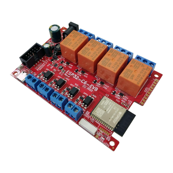
HARDWARE ESP32-C6-EVB layout 4 x Relays with connectors and status Power-good LED LEDs (10A/240VAC max) Power jack input EXT1 header Reset button (8-50)V DC RST1 Boot/User 4 x Opto-coupler inputs with connectors User LED button BUT1 and status LEDs (30V DC max) -
Page 8: Esp32-C6-Evb Schematic
ESP32-C6-EVB schematic The latest ESP32-C6-EVB schematic is available on the next page. You can also download PDF export from GitHu b here All design sources are available also at GitHub here... -
Page 10: Esp32-C6-Evb Power Supply And Consumption
EXT1.pin1 (+5V) note that this wire is connected to the 5V of the USB so when you power ESP32- C6-EVB from EXT1.pin1 – you should not have USB cable attached at the same time!!! The typical power consumption is under 1W. Current consumption of ESP32-C6-EVB is approximately 0.06A when powered by 12V DC (applied to the power jack). -
Page 11: Ext1 Connector (Gpio)
EXT1 connector (GPIO) EXT1 pin #1 is +5V pin; it is usually used as output you can also power the board from this pins BUT ONLY IF the USB-C is not connected! It must be regulated 5V power supply, applying more than 5V will damage the board;... -
Page 12: Uext Connectors
UEXT connector stands for Universal EXTension connector and contains +3.3V output and GND power wires, and I2C, SPI, UART data signals. All signals are at 3.3V levels. ESP32-C6-EVB has two UEXT connectors – UEXT1 and UEXT2, they have the same signals just different connector. -
Page 13: Relays
Relays The board has 4 electro-mechanical relays for analog output, each relay has own status LED. Relay connectors have Normal open, Normal closed, and Common contacts. Relay REL1 is connected to GPIO10 Relay REL2 to GPIO11 Relay REL3 goes to GPIO22 Relay REL4 to GPIO23 Inputs The board has 4 optocouplers for analog input and each input has own status LED. -
Page 14: Esp32-Prog Header
Used to program the board with external serial-USB programmer like (like ESP-PROG) Jumper 3.3V_E1 ESP32-C6-EVB has a single SMT jumpers on-board. SMT jumpers are pads that can be separated (open) or soldered together (closed) to alter the hardware connections of the board and alter the behavior. The SMT jumpers require basic soldering tools and experience, to separate them you need to cut between the pads and to close them you need to solder the pads together. -
Page 15: Software
2) Attach the ESP32-C6-EVB to the computer via USB cable, the cable needs to have USB type C connector at one end and usually USB type A at the other to fit your computer; a lot of devices use similar cables so you might already have such cable at home;... -
Page 16: Document Revision
DOCUMENT REVISION Revision 1.0 August 2023 - initial release...
Need help?
Do you have a question about the ESP32-C6-EVB and is the answer not in the manual?
Questions and answers