Table of Contents
Advertisement
Quick Links
Advertisement
Table of Contents

Subscribe to Our Youtube Channel
Related Manuals for ADInstruments Bio Amp


Summary of Contents for ADInstruments Bio Amp
- Page 1 Bio Amp Owner’s Guide...
- Page 2 MacLab are registered trademarks of ADInstruments Pty Ltd. The names of specific recording units, such as PowerLab 8/30, are trademarks of ADInstruments Pty Ltd. LabTutor Server, Chart and Scope (application programs) and LabTutor Online are trademarks of ADInstruments Pty Ltd.
-
Page 3: Table Of Contents
The Bio Amp Cable ........ - Page 4 The Bio Amp Cable Input ........
-
Page 5: Safety Notes
ADInstruments products are NOT intended to be used as medical devices or in medical environments. That is, no product supplied by ADInstruments is intended to be used to diagnose, treat or monitor a subject. Furthermore no product is intended for the prevention, curing or alleviation of disease, injury or handicap. - Page 6 • All Bio Amp front-ends (except for the ML138 Octal Bio Amp) and PowerLab units with a built-in Bio Amp are supplied with a 3-lead or 5- lead Bio Amp subject cable and lead wire system. The ML138 Octal Bio Amp is supplied with unshielded lead wires (1.8 m).
- Page 7 Isolated Stimulator Safety Instructions The Isolated Stimulator outputs of a front-end signal conditioner or PowerLab with a built-in isolated stimulator are electrically isolated. However, they can produce pulses of up to 100 V at up to 20 mA. Injury can still occur from careless use of these devices.
- Page 8 Therefore, under no circumstances should any other transformer be used with the Stimulus Isolator. For a replacement transformer plug pack please contact your nearest ADInstruments representative. General Safety Instructions To achieve the optimal degree of subject and operator safety, consideration...
- Page 9 Cleaning and Sterilization ADInstruments products may be wiped down with a lint free cloth moistened with industrial methylated spirit. Refer to the manufacturer’s guidelines or the Data Card supplied with transducers and accessories for specific cleaning and sterilizing instructions.
- Page 10 Preventative Inspection and Maintenance PowerLab systems and ADInstruments front-ends are all maintenance-free and do not require periodic calibration or adjustment to ensure safe operation. Internal diagnostic software performs system checks during power up and will report errors if a significant problem is found. There is no need to open the instrument for inspection or maintenance, and doing so within the warranty period will void the warranty.
-
Page 11: Overview
Overview The Bio Amp is a modular device, in a family called front-ends, designed to © extend the capabilities of the PowerLab system. The Bio Amp allows the PowerLab system to record biological signals, such as ECGs (EKGs), EMGs, and EEGs, from humans or animals, with full electrical isolation. This chapter provides an overview of the Bio Amp, Dual Bio Amp and Octal Bio Amp, describing their basic features and the measurement of signals. -
Page 12: How To Use This Guide
It is an integrated system of hardware and software designed to record, display, and analyze experimental data. The Bio Amp is one of a family of front-ends meant for use with your PowerLab system. -
Page 13: The Front-End
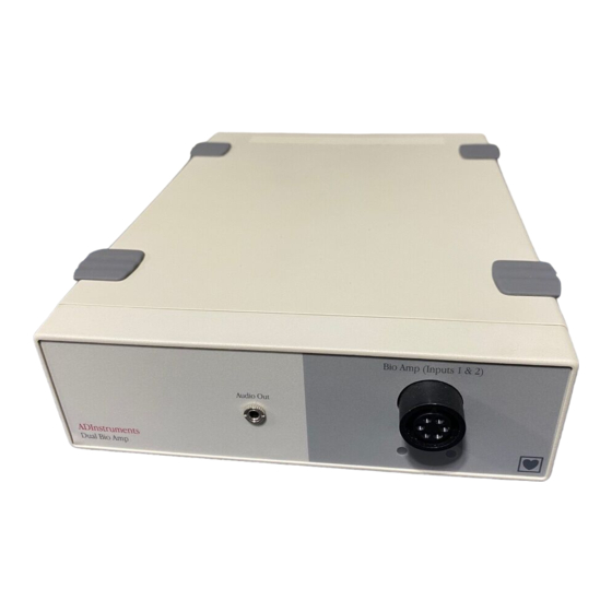
The Front Panel The front panel of a Bio Amp has a single input and an indicator light. The front panel of a Dual Bio Amp has a single input, two indicator lights and an audio output connector. The front panel of the Octal Bio Amp has seventeen single-ended 1.5 mm sockets consisting of eight red connectors, eight black connectors and a single green connector. -
Page 14: The Status Indicator
The Status Indicator The status indicator light of a single Bio Amp is located at the bottom right of the front panel. The status indicator lights of a Dual Bio Amp are located beneath the input connector on the front panel. The status indicator lights of an Octal Bio Amp are located beneath the pair of red and black connectors of each input on the front panel. -
Page 15: Audio Out Socket
The BNC sockets on the back panel of the Bio Amps provide the signal outputs to connected analog input sockets of the PowerLab. The sockets are labeled Signal Output on a single Bio Amp and Output 1 to Output n on a multi-channel Bio Amp. A BNC-to-BNC cable is supplied for each connection. -
Page 16: The Bio Amp Cable
The single Bio Amp is supplied with a 3-lead Bio Amp cable and lead wires. The Dual Bio Amp is supplied with a 5-lead Bio Amp cable and lead wires; it uses a shared ground signal for its Bio Amp inputs. The supplied cables are of the type used for ECG or EMG studies: Tronomed D-1340 or Tronomed D- 1540 cables respectively. -
Page 17: Types Of Measurement
ECG electrodes. The leads are color-coded for identification. The labels on the Bio Amp cable also have color spots to help sort out which cables connect where and what they are measuring. (The colors are arbitrary, since the PowerLab system is for general-purpose recording.) -
Page 18: Recording Technique
Dual Bio Amp, or two Bio Amps. ERG. Electroretinogram; a recording of the electrical signals produced in the retina by a light stimulus. Bilateral measurements require a Dual Bio Amp, or two Bio Amps. Cortical Evoked Potentials. Averaged recordings of the electrical activity of the brain when subject to stimulation: visual evoked response, auditory evoked response, and somatosensory response. - Page 19 Apart from the general areas covered in that material, two things particularly affect the kind of measurements made with the Bio Amp, and can cause ‘artifacts’ (spurious readings) in the recorded waveform: electrode contact and motion effects.
- Page 20 Bio Amp Owner’s Guide...
-
Page 21: Setting Up
Setting Up This chapter describes connecting the Bio Amp to your PowerLab and performing a quick test to make sure that it is working properly. The best way to configure your system for one or more front-ends is discussed, along with how to use the front-end with ADInstruments application programs. -
Page 22: Connecting To The Powerlab
Failure to do this may damage the PowerLab, the front-end, or both. Connect each signal output on the rear panel of the Bio Amp, Dual Bio Amp or Octal Bio Amp, to an analog input on the front panel of the PowerLab using a BNC cable. -
Page 23: Using More Than One Bio Amp
Dual Bio Amp rather than two Bio Amps, and that you use an Octal Bio Amp rather than two or more Dual Bio Amps. Some interaction can take place between individual Bio Amps, causing up to 10 μV of induced low-frequency... -
Page 24: The Front-End Driver
If the indicator or indicators light correctly, the Bio Amp has been found by the PowerLab and is working. If the indicator or indicators don’t light, check the cable connections and repeat the procedure. -
Page 25: The Bio Amp
The Bio Amp The Bio Amp dialog (Figure 2–1 and Figure 2–3) allows software control of the combined input amplifiers and filters in the PowerLab and Bio Amp. The signal present at a channel’s input is displayed in the preview area so that you can see the effects of changes in settings. -
Page 26: Setting The Range
(combined range of the PowerLab and Bio Amp). Changing the range in the Bio Amp dialog is equivalent to changing it in the Chart window. The default setting (if you have not loaded a settings file) is 100 mV and the ranges go down to 5 μV in 14 steps. - Page 27 High Pass High-Pass Filtering. The pop-up menu gives the choice of 0.1, 0.3, 1, 3, and 10 Hz high-pass filters. Dual and Octal Bio Amps have a 0.02 Hz filter as well. The high-pass filter removes frequencies below the chosen frequency and allows high frequencies in the signal.
-
Page 28: Eeg Mode
The waveform in the data display area of the Bio Amp dialog is transferred to the data display area of the Units Conversion dialog. (Use the Pause button to capture a specific signal.) The units conversion only applies to subsequently recorded signals, so it is more limited Units Conversion…... -
Page 29: A Technical Aspects
Amp to give some insight into how it works. You do not need to know the material here to use the Bio Amp. It is likely to be of especial interest to the technically minded, indicating what the front-end can and cannot do, and its suitability for particular purposes. - Page 30 Figure A–1 Block diagram of the Bio Bio Amp Owner’s Guide...
- Page 31 Figure A–2 Block diagram for the Dual Bio Amp and adjacent inputs of the Octal Bio Amp Appendix A Technical Aspects...
-
Page 32: Bio Amp Operation
PowerLab’s input amplifiers. The amplification and ranges offered in LabChart and Scope result from the combination of both pieces of hardware. The Dual Bio Amp is an enhanced double version of the single Bio Amp, with a common power supply and isolated ground. There are some modifications, but it is similar to the Bio Amp overall. -
Page 33: The Bio Amp Cable Input
The Bio Amp Cable Input The Bio Amp cable, for the Bio Amp and Dual Bio Amp, plugs into the six- pin input socket on the front panel of the Bio Amp. A notch in the plug ensures that polarity is correct. Only the supplied Bio Amp cable and lead wires should be used as other cables may not meet safety requirements. - Page 34 CH2 Positive (+) CH1 Negative (–) The Octal Bio Amp has a pair of connectors for each of the eight Bio Amp inputs, and a single connector for the shared ground. The connectors are physically and electrically isolated to ensure subject safety. The Octal Bio Amp should be used with the supplied 1.8 m unshielded lead wires.
-
Page 35: B Troubleshooting
Troubleshooting This appendix describes most of the common problems that can occur when using the Bio Amp with your PowerLab recording unit. It covers how these problems are caused, and what you can do to alleviate them. If the solutions here do not work, earlier chapters, the LabChart Help Center, and the guide to your PowerLab may contain possible remedies. -
Page 36: Problems And Solutions
On starting up the software, an alert indicates that there is a problem with the front-end or driver The correct Bio Amp driver is not installed on your computer (it should be in the Essential Files folder in the LabChart or Scope folder). - Page 37 • Check the connections for proper contact and try again. If you are using the Dual Bio Amp or the Octal Bio Amp, with the 0.02 Hz high-pass filter, the trace can take a long time to zero by itself.
- Page 38 • Make sure the settings are appropriate for the expected signal. You may be using the wrong Bio Amp cable for the type of input. The single Bio Amp and Dual Bio Amp have different pin arrangements, so their Bio Amp cables are not interchangeable.
-
Page 39: C Specifications
1 isolated differential channel with isolated ground reference Ω Input impedance: 200 M differential, 30 pF (no cable) or 500 pF (supplied Bio Amp cable and leads) to isolated ground Isolation: 4000 V (50 Hz for 1 minute) Amplification ranges: ±... -
Page 40: Filtering
Control Port C port: Provides control and power. Interface communications rate of ~50 kbits/s. Physical Configuration × × × × Dimensions (h 50 mm 76 mm 260 mm × × (1.97" 3.0" 10.2") Bio Amp Owner’s Guide... -
Page 41: Safety
2 isolated differential channels with common isolated ground reference Ω Input impedance: 200 M differential, 30 pF (no cable) or 500 pF (supplied Bio Amp cable and leads) to isolated ground Isolation: 4000 V (50 Hz for 1 minute) Amplification ranges: ±... -
Page 42: Filtering
Frequencies software-selectable. Standard: 0.02, 0.1, 0.3, 1, 3, & 10 Hz (@ –3 dB); EEG mode: 0.03, 0.1, 0.3 & 1 seconds Notch filter: Second-order filter, –32 dB attenuation; 50 or 60 Hz frequency (automatic sensing) Bio Amp Owner’s Guide... -
Page 43: Output
RF or strong magnetic fields that may cause interference. Method of Disposal: Forward to recycling centre or return to manufacturer. Octal Bio Amp Input Connection type: 17 x 1.5 mm pin shrouded male socket to suit single pin 1.5 mm... - Page 44 Isolation: 4000 V (50 Hz for 1 minute) Amplification ranges: ± 5 μV to ± 100 mV full scale in 14 steps (combined PowerLab and Bio Amp) ± 100 mV ± 50 mV ± 20 mV ± 10 mV ± 5 mV ±...
-
Page 45: Filtering
Filtering Low-pass filtering: Fourth-order Bessel filter, ± 3% accuracy. Frequencies software-selectable. Standard: 50, 100, 200, 500, 1000, 2000, & 5000 Hz (@ –3 dB); EEG mode: 3, 10, 30, 60, & 120 Hz High-pass filtering: First-order filter, ± 0.25% accuracy. Frequencies software-selectable. - Page 46 - air mixtures. Avoid operating near high voltage, RF or strong magnetic fields that may cause interference. Method of Disposal: Forward to recycling centre or return to manufacturer. ADInstruments reserves the right to alter these specifications at any time. Bio Amp Owner’s Guide...
-
Page 47: Electromagnetic Compatibility
Electromagnetic Compatibility The ML138 Octal Bio Amp (the device) has been tested to comply with the requirements of IEC 60601-1-2, IEC 61000-3-2, IEC 61000-3-3, IEC 61000-4- 2, IEC 61000-4-3, IEC 61000-4-4, IEC 61000-4-5, IEC 61000-4-6, IEC 61000- 4-8, IEC 61000-4-11 and CISPR 11. - Page 48 Bio Amp Owner’s Guide...
-
Page 49: Index
Index ADInstruments programs 23–28 input socket 33 aliasing 27 I2C bus 13, 15, 32 analog output 15 Application Notes 17 LabChart 23, 27 artifacts 19 audio output 15 maintenance 10 measurements 17–18 back panel 15 Cortical Evoked Potentials 18 Bio Amp ECG (EKG) 17 cable 16–17... - Page 50 14 storage 10 technical specifications 39–46 triboelectric effects 19 user modification voids warranty 29 using ADInstruments programs 23–28 using this guide 12 Bio Amp Owner’s Guide...
Need help?
Do you have a question about the Bio Amp and is the answer not in the manual?
Questions and answers