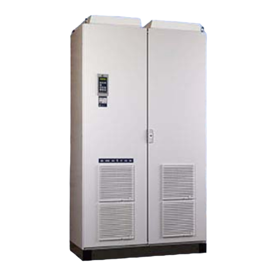
Emotron VFX 2.0 Instruction Manual
Variable speed drive
Hide thumbs
Also See for VFX 2.0:
- Quick setup (2 pages) ,
- Instruction manual (194 pages) ,
- Instruction manual (98 pages)
Table of Contents
Advertisement
Quick Links
Advertisement
Table of Contents

Summary of Contents for Emotron VFX 2.0
- Page 1 Variable Speed Drive VFX 2.0 Instruction Manual - English...
- Page 2 Date of release: 25-08-2006 © Copyright Emotron AB 2005 - 2006 Emotron retains the right to change specifications and illustrations in the text, without prior notification. The contents of this document may not be copied without the explicit permission of Emotron AB.
- Page 4 Type B packaging during transport. This packaging is specially RCD is allowed on the supply side of this product. Use designed to absorb shocks during transport. RCD of 300 mA minimum. Emotron AB 01-3695-01r1a...
- Page 5 IT Mains supply The variable speed drives can easily be connected to a IT mains supply, (non-earthed neutral), please contact your supplier for details. Emotron AB 01-3695-01r1a...
-
Page 6: Table Of Contents
Editing values in a menu ........44 Connect the mains and motor cables....25 Programming example..........45 5.1.1 Mains cables ............25 Serial communication........47 5.1.2 Motor cables............25 10.1 Description of the EInt formats ......47 Connect control cables ........... 25 Emotron AB 01-3695-01r1a... - Page 7 11.9.3 Reset Trip Log [8A0] ..........132 11.10 System Data [900]..........132 11.10.1 VSD Data [920] ............. 132 Troubleshooting, Diagnoses and Maintenance..........135 12.1 Trips, warnings and limits........135 12.2 Trip conditions, causes and remedial action ..136 12.2.1 Technically qualified personnel......136 Emotron AB 01-3695-01r1a...
-
Page 8: Introduction
Introduction Emotron VFX is intended for controlling the speed and The variable speed drives are delivered with a template for torque of standard three phase asynchronous electrical positioning the fixing holes on a flat surface. Check that all motors. The VSD is equipped with a sophisticated vector items are present and that the type number is correct. -
Page 9: Standards
Low Voltage Directive: Declaration of Conformity and CE marking Classification of environmental conditions. Air quality chemical vapours, unit in operation. Chemical gases 3C1, Solid particles 3S2. IEC 60721-3-3 Optional with coated boards Unit in operation. Chemical gases Class 3C2, Solid particles 3S2. Introduction Emotron AB 01-3695-01r1a... -
Page 10: Dismantling And Scrapping
For more detailed information about recycling this product, please contact the local distributor of the product or visit our home page www.emotron.com. Glossary 1.6.1 Abbreviations In this manual the following abbreviations are used:... - Page 11 Introduction Emotron AB 01-3695-01r1a...
-
Page 12: Mounting
The VSD must be mounted in a vertical position against a flat surface. Use the template (delivered together with the VSD) to mark out the position of the fixing holes. Fig. 2 Recommended Fig. 4 Variable speed drive mounting models 003 to 250 Emotron AB 01-3695-01r1a Mounting... -
Page 13: Cooling
Cable interface for mains, motor and communication, VSD models 003 - 010 (X1) VFX-VFX (mm) 23,75 128,5 VFX-wall (mm) 2.2.2 Mounting schemes Fig. 7 VSD models 013 - 037 (S2) Fig. 5 VSD models 003 - 010 (X1) Mounting Emotron AB 01-3695-01r1a... - Page 14 Cable interface for mains, motor and communication, VSD models 013 - 037 (S2). Glands 284,50 22,50 Fig. 11 VSD models 090 - 175 including cable interface for mains, motor and communication (E) Fig. 9 VSD models 046 - 073 (X2) Emotron AB 01-3695-01r1a Mounting...
-
Page 15: Cabinet Mounting
003 – 010 013 – 037 046 – 073 Fig. 13 A VSD with a control panel mounted in the cabinet door 090 – 175 210 – 250 NOTE: The RS232 cable is a standard cable. Mounting Emotron AB 01-3695-01r1a... -
Page 16: Installation
• Use screened cables according to specification in table 7. • Use heat-resistant cables, +60°C or higher. • Dimension the cables and fuses in accordance with the nominal output current of the motor. See table 41, page 152. • Maximum length of the motor cable. Emotron AB 01-3695-01r1a Installation... - Page 17 VSD built into a cabinet. Metal cable glands Screened cables Metal housing Output Brake resistor coils (option) (option) Metal connector housing Metal cable gland Motor Mains Fig. 17 Variable speed drive as stand alone Installation Emotron AB 01-3695-01r1a...
-
Page 18: Mains Cables
RFI mains filter that complies with the 2nd environment standard. Table 8 Stripping lengths for mains and motor cables OPTION Mains cable Motor cable Model (mm) (mm) (mm) (mm) (mm) L2 L3 PE 003–010 013–037 046–073 Fig. 18 Mains and motor connections 090-175 210–250 Emotron AB 01-3695-01r1a Installation... -
Page 19: Dimension Of Cables And Fuses
4. Connect and tighten the cable in the clamp. 5. Put the cable interface in place and secure with the screws. Table 11 Model 210 to 250 Brake chopper Mains/motor Block, mm Cable diameter, mm 35-95 120-150 35-70 95-240 Tightening torque, Nm Installation Emotron AB 01-3695-01r1a... -
Page 20: Thermal Protection On The Motor
Menu [227] Set the average Cos PHI value for the Motor Cos PHI: motors in parallel. NOTE: The shafts of the motors in parallel must be physically connected to obtain correct torque and speed control. Emotron AB 01-3695-01r1a Installation...


Need help?
Do you have a question about the VFX 2.0 and is the answer not in the manual?
Questions and answers