Sign In
Upload
Manuals
Brands
Emotron Manuals
Controller
VFX 2.0
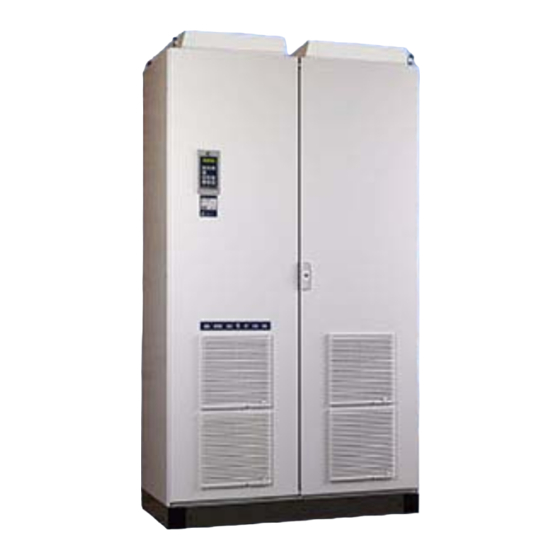
Emotron VFX 2.0 Manuals
Manuals and User Guides for Emotron VFX 2.0. We have
3
Emotron VFX 2.0 manuals available for free PDF download: Instruction Manual, Quick Setup
Emotron VFX 2.0 Instruction Manual (194 pages)
Variable Speed Drive
Brand:
Emotron
| Category:
Inverter
| Size: 8 MB
Table of Contents
Safety Instructions
9
Table of Contents
11
Contents
11
1 Introduction
13
Delivery and Unpacking
13
Using of the Instruction Manual
13
Type Code Number
13
Standards
14
Product Standard for EMC
14
Dismantling and Scrapping
15
Disposal of Old Electrical and Electronic Equipment
15
Glossary
16
Abbreviations and Symbols
16
Definitions
16
2 Mounting
17
Lifting Instructions
17
Stand-Alone Units
18
Cooling
18
Mounting Schemes
19
Cabinet Mounting
21
Cooling
21
Mounting Schemes
21
3 Installation
23
Before Installation
23
Cable Connections for 003 to 073
23
Mains Cables
23
Motor Cables
24
Connect Motor and Mains Cables for 090 to 1500
26
Cable Specifications
27
Stripping Lengths
27
Dimension of Cables and Fuses
27
Tightening Torque for Mains and Motor Cables
27
Thermal Protection on the Motor
28
Motors in Parallel
28
4 Control Connections
29
Control Board
29
Terminal Connections
30
Inputs Configuration with the Switches
30
Connection Example
31
Connecting the Control Signals
32
Cables
32
Types of Control Signals
33
Screening
33
Single-Ended or Double-Ended Connection
33
Current Signals ((0)4-20 Ma)
34
Twisted Cables
34
Connecting Options
34
5 Getting Started
35
Connect the Mains and Motor Cables
35
Mains Cables
35
Motor Cables
35
Using the Function Keys
35
Remote Control
36
Connect Control Cables
36
Switch on the Mains
36
Set the Motor Data
36
Run the VSD
36
Local Control
37
Switch on the Mains
37
Select Manual Control
37
Set the Motor Data
37
Enter a Reference Value
37
Run the VSD
37
6 Applications
39
Application Overview
39
Cranes
39
Crushers
39
Mills
40
Mixers
40
7 Main Features
41
Parameter Sets
41
One Motor and One Parameter Set
42
One Motor and Two Parameter Sets
42
Two Motors and Two Parameter Sets
42
Autoreset at Trip
42
Reference Priority
42
Preset References
43
Remote Control Functions
43
Performing an Identification Run
45
Using the Control Panel Memory
45
Load Monitor and Process Protection [400]
46
Load Monitor [410]
46
8 EMC and Machine Directive
49
EMC Standards
49
Stop Categories and Emergency Stop
49
9 Operation Via the Control Panel
51
General
51
The Control Panel
51
The Display
51
Indications on the Display
52
LED Indicators
52
Control Keys
52
The Toggle and Loc/Rem Key
52
Function Keys
54
The Menu Structure
54
The Main Menu
54
Programming During Operation
55
Editing Values in a Menu
55
Copy Current Parameter to All Sets
55
Programming Example
56
10 Serial Communication
57
Modbus RTU
57
Parameter Sets
57
Motor Data
58
Start and Stop Commands
58
Reference Signal
58
Description of the Eint Formats
58
11 Functional Description
63
Preferred View [100]
63
1St Line [110]
63
Modbus Instance No/Devicenet no
63
2Nd Line [120]
64
Main Setup [200]
64
Operation [210]
64
Modbus Instance No/Devicenet no
64
Max Speed
65
Remote Signal Level/Edge [21A]
67
Mains Supply Voltage [21B]
68
Motor Data [220]
68
Maximum Speed [343
69
Motor Protection [230]
72
Parameter Set Handling [240]
75
Trip Autoreset/Trip Conditions [250]
77
Serial Communication [260]
83
Process and Application Parameters [300]
86
Set/View Reference Value [310]
86
Process Settings [320]
86
Start/Stop Settings [330]
90
Mechanical Brake Control
94
Speed [340]
96
Maximum Speed [343
97
Torques [350]
99
Preset References [360]
100
PI Speed Control [370]
101
PID Process Control [380]
102
Pump/Fan Control [390]
106
Crane Option [3A0]
112
Load Monitor and Process Protection [400]
114
Load Monitor [410]
114
Process Protection [420]
118
I/Os and Virtual Connections [500]
120
Analogue Inputs [510]
120
Digital Inputs [520]
127
Analogue Outputs [530]
128
Digital Outputs [540]
132
Relays [550]
133
Virtual Connections [560]
134
Logical Functions and Timers [600]
135
Comparators [610]
135
Logic Output y [620]
139
Logic Output Z [630]
141
Timer1 [640]
142
Timer2 [650]
144
View Operation/Status [700]
145
Operation [710]
145
Status [720]
147
Stored Values [730]
150
View Trip Log [800]
151
Trip Message Log [810]
151
Trip Messages [820] - [890]
152
Reset Trip Log [8A0]
153
System Data [900]
153
VSD Data [920]
153
12 Troubleshooting, Diagnoses and Maintenance
155
Trips, Warnings and Limits
155
Trip Conditions, Causes and Remedial Action
156
Technically Qualified Personnel
156
Opening the Variable Speed Drive
156
Precautions to Take with a Connected Motor
156
Autoreset Trip
156
Maintenance
159
13 Options
161
Options for the Control Panel
161
Emosoftcom
161
Brake Chopper
161
I/O Board
163
Output Coils
163
Serial Communication and Fieldbus
163
Standby Supply Board Option
163
Safe Stop Option
163
Crane Option Board
165
Encoder
165
Ptc/Pt100
165
14 Technical Data
167
Electrical Specifications Related to Model
167
General Electrical Specifications
171
Operation at Higher Temperatures
172
Dimensions and Weights
173
Environmental Conditions
174
Fuses, Cable Cross-Sections and Glands
175
According IEC Ratings
175
Fuses and Cable Dimensions According NEMA Ratings
177
Control Signals
179
15 Menu List
181
Index
189
Advertisement
Emotron VFX 2.0 Instruction Manual (98 pages)
Fieldbus Option
Brand:
Emotron
| Category:
DC Drives
| Size: 1 MB
Emotron VFX 2.0 Quick Setup (2 pages)
Brand:
Emotron
| Category:
Controller
| Size: 0 MB
Advertisement
Advertisement
Related Products
Emotron VS30
Emotron VSB Series
Emotron VBS48-003-20CNB
Emotron VSB23-008-20CNB
Emotron VSU48-004-20CNB
Emotron VSU23-003-20CNB
Emotron VSU23-008-20CNB
Emotron VSU23-011-20CNB
Emotron VSU23-005-20CNB
Emotron VFX 2.1
Emotron Categories
DC Drives
Controller
Inverter
Control Unit
Servo Drives
More Emotron Manuals
Login
Sign In
OR
Sign in with Facebook
Sign in with Google
Upload manual
Upload from disk
Upload from URL