Table of Contents
Advertisement
Quick Links
Advertisement
Table of Contents

Related Manuals for Emotron EMX-D


Summary of Contents for Emotron EMX-D
- Page 2 Emotron EMX-D Drive system for rotary heat exchanger Instruction manual English...
- Page 4 Addendum Addendum valid for Emotron EMX-D This addendum belongs to the instruction manual with document number: 01-5016-01r0 for Emotron EMX-D Installation of the drive unit (motor plus reduction gear) • Mount the drive unit. lubricant in the gearbox is 0,25 litre.
- Page 5 Addendum Select language Language [211] As default, the language in the control panel display and Select the language used in menu system and menu system is set to English. One of the first things to do on the LCD display. during commissioning is to select desired language in the system.
- Page 6 Date of release: 2010-09-01 © Copyright Emotron AB 2010 Emotron retains the right to change specifications and illustrations in the text, without prior notification. The contents of this document may not be copied without the explicit permission of Emotron AB.
-
Page 8: Safety Instructions
All installa- tion descriptions in this manual follow the EMC Directive. Voltage tests (Megger) Do not carry out voltage tests (Megger) on the motor, before all the motor cables have been disconnected from the drive system. Emotron AB 01-5016-01r0... - Page 9 Emotron AB 01-5016-01r0...
-
Page 10: Table Of Contents
The main menu ............23 Programming during operation ......23 General description ........7 Editing values in a menu ........23 Emotron EMX -D is available with different Programming example..........24 gearboxes ..............7 Accessories..............7 Functional Description ........ 27 Built-in functions ............ - Page 11 Emotron AB 01-5016-01r0...
-
Page 12: Introduction
Introduction Standards Emotron EMX-D is a speed-controlled drive system spe- cially designed for driving rotary heat-exchangers. The sys- The variable speed drives described in this instruction man- tem comprises an enclosed control unit and a motor unit ual comply with the standards listed in Table 1. For the dec- with worm reduction gear, which are linked by two cables. -
Page 13: Dismantling And Scrapping
The recycling of materials will help to con- serve natural resources. For more detailed information about recycling this product, please contact the local distributor of the product or visit our home page www.emotron.com. Introduction Emotron AB 01-5016-01r0... -
Page 14: General Description
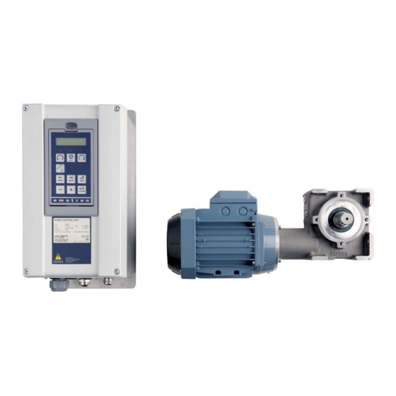
General description Emotron EMX-D is a speed-controlled drive system spe- cially designed for driving rotary heat-exchangers. The sys- Motor speed tem comprises an enclosed control unit and a motor unit - 100% 135 rpm with worm reduction gear, which are linked by two cables. -
Page 15: Built-In Functions
0-10 V or 0-20 mA in proportion to the speed of outgoing shaft. 2.3.7 Absolute humidity The humidity sensor (Not included in Emotron delivery) is connected to an external transducer and controls the motor speed by means of control signal input. -
Page 16: Installation
The rotation sensor is mounted to ensure that the magnet passes over it at a distance of 5-8 Fig. 4 Emotron motor and Control unit for rotary heat mm, see Fig. 6 . exchangers Choice of pulley diameter... -
Page 17: Cable Connections
12 13 14 15 16 17 18 19 20 21 22 41 42 43 52 53 31 32 33 Screen connection of motor cables Mains connection Motor cables connection Fig. 7 Mains, motor and PTC connections to Control unit. Installation Emotron AB 01-5016-01r0... -
Page 18: Emc Recommendations
Compatibility (EMC) stipulated in the European directive 2004//EEC, it is essential to follow the instructions adhered to. EMX-D features an integral EMC filter. The following should be observed for EMX-D: • Screened cable must be used for the motor cable, the PTC cable the control cable and the cable to the rotation monitor. - Page 19 Installation Emotron AB 01-5016-01r0...
-
Page 20: Control Connections
Control Panel Switches Relay outputs Control signals Not used Not used Fig. 10 Control board layout Emotron AB 01-5016-01r0 Control Connections... -
Page 21: Terminal Connections
Relay 1 output COM 1 Trip, active when the VSD is in a TRIP condition. N/O 1 NOTE: N/C is opened when the relay is active and N/O is closed when the relay is active. Control Connections Emotron AB 01-5016-01r0... -
Page 22: Connection Example
+24 VDC Relay 1 Common Rotation monitor DigIn 4: Rotation monitor DigIn 5: Priority switch DigIn 6: Max. speed RESET LOC/ PREV NEXT ENTER * The switch S1 is set to U Fig. 11 Connection example Emotron AB 01-5016-01r0 Control Connections... -
Page 23: Cables
90 angle. Do not let NOTE: Control cables must be separated from motor and mains cables. the signal cable go in parallel with the mains and motor cable. Control Connections Emotron AB 01-5016-01r0... -
Page 24: Current Signals ((0)4-20 Ma)
The control sig- nal can of course also be reduced to its minimum value, in order to achieve the same result. If the control signal is low or absent the drive system switches to purging mode. Emotron AB 01-5016-01r0 Control Connections... - Page 25 Control Connections Emotron AB 01-5016-01r0...
-
Page 26: Getting Started
2. For remote control, remove the jumper and connect an external start button between terminal 11 and 9 as in Fig. 14. If you would like the motor to run left, use ter- minal 11 and 8 instead. Emotron AB 01-5016-01r0 Getting Started... -
Page 27: Using The Function Keys
NEXT NEXT step to previous menu on the same level PREV PREV increase value or change selection decrease value or change selection Getting Started Emotron AB 01-5016-01r0... -
Page 28: Operation Via The Control Panel
Area A: Shows the actual menu number (3 digits). Area B Indicates if the menu is in the toggle loop. Area C Rotation monitor Indicators, flashing each time rotation sensor is activated. Emotron AB 01-5016-01r0 Operation via the Control Panel... -
Page 29: Led Indicators
For instance, a menu can have one selectable menu (View Reference Value [310]), or it can have 10 selectable menus (menu Operation [710]). NOTE: If there are more than 10 menus within one level, the numbering continues in alphabetic order. Operation via the Control Panel Emotron AB 01- 01-5016-01r0... -
Page 30: The Main Menu
Viewing the last 10 trips in the trip memory. is suitable when you want to make large changes, i.e. from 200 s to 30 s. O00 EMX-D Options Settings for the operation are changed in these menus. Example: When you press Next the 4 will blink. -
Page 31: Programming Example
If at this moment, the power fails, the change will not be saved. Use the ESC, Prev or Next keys to proceed and to go to PREV other menus. O00 EMX-D option Example 1 Press Prev for menu [O00]. Shut off the rotation sensor... - Page 32 Normal Normal Menu 100 appears Menu 100 appears 29,5 rpm after power-up. 29,5 rpm after power-up. PREV PREV O00 EMX-D option O00 EMX-D option Press Prev for menu Press Prev for menu [O00]. [O00]. ENTER ENTER EMX-D Pars EMX-D Pars...
- Page 33 Operation via the Control Panel Emotron AB 01- 01-5016-01r0...
-
Page 34: Functional Description
Functional Description EMX-D Options[O00] This chapter describes the menus and parameters in the soft- ware. You will find a short description of each function and This menu contains special features for the rotating heat information about default values, ranges, etc. - Page 35 MCC speed ing. 6.5 rpm O17 Hold torque Default: 6.5 rpm Range 0 - 200 rpm Default: Resolution 0.01 rpm No hold torque Hold torque on Functional Description Emotron AB 01-5016-01r0...
-
Page 36: Main Setup [200]
Displays the actual shaft power. Shows active reference value. 714 Shaft Power 7.4.1 View Reference speed [310] In this menu [310] the value of the active reference signal is displayed. Unit: Resolution: 310 View ref 0rpm Default: 0 rpm Emotron AB 01-5016-01r0 Functional Description... -
Page 37: Status [720]
Parameter Set A is active. Rem: Reference value comes from terminals 1-22. DC Link Voltage [719] Rem: Run/Stop commands come from terminals 1-22. Displays the actual DC link voltage. Torque Limit active. 719 DC Voltage Unit: Resolution: Functional Description Emotron AB 01-5016-01r0... - Page 38 1 DigOut1 based on the full range/scale of the in- our output; so 2 DigOut2 related to either 0–10 V or 0–20 mA. The status of the associated output is shown. 1 High 0 Low Emotron AB 01-5016-01r0 Functional Description...
-
Page 39: Stored Values [730]
7.6.1 Trip Message log [810] Display the cause of the trip and what time it occurred. When a trip occurs the status menus are copied to the trip Functional Description Emotron AB 01-5016-01r0... -
Page 40: Reset Trip Log [8A0]
Reset Trip Log [8A0] Resets the content of the 9 trip memories. 8A0 Reset Trip Default: NOTE: After the reset the setting goes automatically back to “NO”. The message “OK” is displayed for 2 sec. Emotron AB 01-5016-01r0 Functional Description... - Page 41 Functional Description Emotron AB 01-5016-01r0...
-
Page 42: Troubleshooting, Diagnoses And Maintenance
Sometimes the so-called “Trial and error” method is a quicker way to determine the cause of the failure. This can be done at any level, from changing settings and functions to disconnecting single control cables or replacing entire drives. Emotron AB 01-5016-01r0 Troubleshooting, Diagnoses and Maintenance... -
Page 43: Technically Qualified Personnel
VSD for repair. The connections for the control signals and the switches are isolated from the mains voltage. Always take adequate pre- cautions before opening the variable speed drive. Troubleshooting, Diagnoses and Maintenance Emotron AB 01-5016-01r0... - Page 44 Peak voltage on DC link Power Fault Error on power board. Check mains supply voltage Check for clogged air inlet filters in panel door and Fan Error Error in fan module blocking material in fan module. Emotron AB 01-5016-01r0 Troubleshooting, Diagnoses and Maintenance...
-
Page 45: Maintenance
Check this and clean the heat sink and the fans when necessary. If variable speed drives are built into cabinets, also check and clean the dust filters of the cabinets regularly. Check external wiring, connections and control signals. Tighten terminal screws if necessary. Troubleshooting, Diagnoses and Maintenance Emotron AB 01-5016-01r0... -
Page 46: Technical Data
Table 11: Model designations Order Gear Torque Shaft Name Reduction number gear length* 01-5071-00 EMX-D Motor 10.3:1 10.3:1 8 - 200 rpm 26 Nm 40 mm 01-5071-10 EMX-D Motor 10.3:1 10.3:1 8 - 200 rpm 26 Nm 60 mm 01-5072-00 EMX-D Motor 15.5:1... -
Page 47: Dimensions
Dimensions 128.5 Caution 202.6 Fig. 36 Dimensions, control unit * EMX-D Gearbox 10.3:1: 146 mm EMX-D Gearbox 10.3:1: 166 mm EMX-D Gearbox 15.5:1: 146 mm Fig. 37 Dimensions, motor and gearbox (mm) Technical Data Emotron AB 01-5016-01r0... -
Page 48: Control Signals
N/C is opened when the relay is active relay output 0.1 – 2 A/U 250 VAC or 42 VDC (valid for all relays) N/O 1 N/O is closed when the relay is active (valid for all relays) Emotron AB 01-5016-01r0 Technical Data... - Page 49 Technical Data Emotron AB 01-5016-01r0...
-
Page 50: Menu List
10. Menu List DEFAULT CUSTOM Output voltage Frequency DEFAULT CUSTOM DC Link voltage EMX-D Options Heatsink Tmp EMX-D Pars FI Status Rot Sensor DigIn status G-box ratio 10.3 DigOut status Mot Max Speed 200 rpm AnIn status 1 2 Mot Prio Ref... - Page 51 Menu List Emotron AB 01-5016-01r0...
-
Page 52: Index
(732) .........32 Editing values ........23 (733) .........32 Electrical specification ......39 (800) .........32 (810) .........32 Twisted cables ......17 (811-81N) ........32 EMX-D Pars ........27 (830) Over temp .......33 EN60204-1 ........6 (8A0) ........33 EN61800-3 ........6 (O00) ........43 EN61800-5-1 ........6 (O10) ........27 (O11) ........27 (O12) ........27... - Page 53 Emotron AB, Mörsaregatan 12, SE-250 24 Helsingborg, Sweden Tel: +46 42 16 99 00, Fax: +46 42 16 99 49 E-mail: info@emotron.se Internet: www.emotron.com...
Need help?
Do you have a question about the EMX-D and is the answer not in the manual?
Questions and answers