Table of Contents
Advertisement
Quick Links
TABLE OF CONTENTS
1. INTRODUCTION .....................................................................
1.1 Key Features..................................................................
1.2 Checklist.......................................................................
1.3 Static Electricity Precautions...............................................
2. HARDWARE CONFIGURATION.................................................
2.1 Mainboard Layout...........................................................
2.2 Installing CPU...............................................................
2.3 How to Set Jumper..........................................................
2.4 Jumpers & Connectors......................................................
2.4.1 ATX Mainboard..................................................
2.4.2 Baby AT Mainbard...............................................
2.5 Memory Configuration......................................................
3. AWARD BIOS SETUP...............................................................
3.1 Standard CMOS Setup......................................................
3.2 BIOS Features Setup........................................................
3.3 Chipset Features Setup.....................................................
3.4 Power Management Setup.................................................
3.5 PNP/PCI Slot Configuration...............................................
3.6 Load Setup Defaults........................................................
3.7 Integrated Peripherals Setup...............................................
3.8 User Password Setup.......................................................
3.9 IDE HDD Auto Detection..................................................
3.10 CPU Speed Setup..........................................................
3.11 Save and Exit Setup........................................................
3.12 Exit without Saving......................................................... 41
4. DRIVER INSTALLATION..........................................................
Appendix I..................................................................................
INTEL PII
User's Guide
1
1
3
3
4
4
12
13
13
15
19
23
24
25
27
30
32
34
36
36
38
39
40
41
42
45
Advertisement
Table of Contents

Related Manuals for Pine Technology TL-BX31

Summary of Contents for Pine Technology TL-BX31
-
Page 1: Table Of Contents
INTEL PII User’s Guide TABLE OF CONTENTS 1. INTRODUCTION …………………………………………………………… 1.1 Key Features………………………………………………………… 1.2 Checklist…………..………………………………………………… 1.3 Static Electricity Precautions……………………………………….. 2. HARDWARE CONFIGURATION…………………………………………. 2.1 Mainboard Layout………………………………………………….. 2.2 Installing CPU……………………………………………………… 2.3 How to Set Jumper…………………………………………………. 2.4 Jumpers & Connectors……………………………………………… 2.4.1 ATX Mainboard………………………………………….. 2.4.2 Baby AT Mainbard……………………………………….. -
Page 2: Introduction
IBM PC/AT compatible. KEY FEATURES This manual applies to different models of Intel chipset mainboard. Please refer to appropriate section and mainboard layout according to the model no. Model No. TL-BX31 TL-ZX31 TL-BX21 TL-ZX21 Chipset i440BX... - Page 3 INTEL PII User’s Guide Form Factor Baby AT Model No. TL-IBX3-13 TL-IZX3-13 TL-IBX2-13 TL-IZX2-13 Chipset i440BX i440ZX I440BX i440ZX Socket Socket 370 Front-Side Bus 66 / 100 MHz Processor INTEL Socket 370 Celeron A 300 MHz or abover Processor CPU Speed Jumperless setting Voltage Regulator...
-
Page 4: Checklist
INTEL PII User’s Guide Yamaha 128 Voice SoftSynth Software The Yamaha Software Synthesizer S-YXG50 makes it possible for computers with MMX technology to playback MIDI data with higher sound quality than ever. Even to CD quality level without using hardware. As it also supports DirectSound as well, you can also enjoy the sound effects from the latest DirectSound multimedia games. -
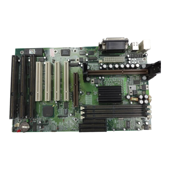
Page 5: Hardware Configuration
This chapter describes how to set jumpers and install memory modules, and where to attach components. **You can find the Model No. label on the mainboard.** MAINBOARD LAYOUT Model No: TL-BX31 LO WER: C OM1 C O M2 KEYBO ARD... - Page 6 INTEL PII User’s Guide PS/2 Keyboard USB Port 2 Serial Port 1 / 2...
- Page 7 INTEL PII User’s Guide Model No: TL-ZX31 LO WER: C O M1 C O M2 KEYBO ARD USB 0/1 J 25 LPT 1 BIOS J 21 UPPER: J 27 PS2 MO USE J 26 ATX POWER CONNECTOR SLO T 1 DIMM0 Intel PC Iset DIMM1...
- Page 8 INTEL PII User’s Guide Model No.: TL-BX21 Jp13 Floppy J 32 J 31 ATX-From card J 30 Intel PC Iset Speaker J 23 J 25 IDE1IDE2 JP11 HD-LED “Normal”...
- Page 9 INTEL PII User’s Guide Model No.: TL-ZX21 Jp13 Floppy J 32 J 31 ATX-From card J 30 Intel PC Iset Speaker J 23 J 25 IDE1IDE2 JP11 HD-LED “Normal”...
- Page 10 INTEL PII User’s Guide Model No.: TL-IBX3-13 LOWER: C O M1 C O M2 KEYBOARD USB 0/1 LPT 1 BIOS J 21 UPPER: J 27 PS2 MO USE SLO T 1 DIMM0 Intel PCIset DIMM1 J P11 Speaker “Normal” DIMM2 RT C Floppy J 1 IDE2...
- Page 11 INTEL PII User’s Guide Model No.: TL-IZX3-13 LOWER: C O M1 C O M2 KEYBOARD USB 0/1 LPT 1 BIOS J 21 UPPER: J 27 PS2 MO USE SLO T 1 DIMM0 Intel PCIset DIMM1 J P11 Speaker “Normal” Floppy J 1 RT C IDE2 PWR+...
- Page 12 INTEL PII User’s Guide Model No.: TL-IBX2-13 Jp13 Floppy J 32 J 31 ATX-From card J 30 Intel PC Iset Speaker J 25 IDE1 IDE2 JP11 HD-LED “Normal”...
- Page 13 INTEL PII User’s Guide Model No.: TL-IZX2-13 Jp13 Floppy J 32 J 31 ATX-From card J 30 Intel PC Iset Speaker J 25 IDE1 IDE2 JP11 HD-LED “Normal”...
-
Page 14: Installing Cpu
INTEL PII User’s Guide INSTALLING CPU This mainboard supports the Pentium II CPU using Single Edge Contact (SEC) slot and Socket 370. Slot 1 To install the CPU, flatten the two latches on the side of the CPU, insert the CPU into the retention clip. -
Page 15: How To Set Jumper
INTEL PII User’s Guide HOW TO SET JUMPER Jumper switch is used to select between various operating modes. A jumper switch consists of two or three gold pins, which stretches out from the system board. By using the cap to cover two pins is to short those pins. - Page 16 INTEL PII User’s Guide Selecting the CPU Frequency The possible settings of current CPU available on the market are listed below, and pls verify the BIOS – “CPU SPEED SETTING” to set the correct CPU Clock+Ratio. Pentium II / Celeron A CLock Ratio 233MHz...
-
Page 17: Atx Mainboard
INTEL PII User’s Guide 2.4.1 ATX Mainboard CPU FAN connector (P4) Plug in the fan cable to the 3-pin fan connector onboard. The fan connector is marked CPU FAN and FAN on the system board. Pin1 Sense Pin2 +12V Pin3 Flash ROM Voltage Selector (J25) Description 12v (default) - Page 18 INTEL PII User’s Guide ATX power connector pinout The ATX power supply provides a single 20-pin connector. Description Description 3.3V 3.3V 3.3V -12V Ground Ground PS-ON Ground Ground Ground Ground Ground Power OK 5VSB +12V Note: Some ATX-Power does not have –5V voltage output, it will effect some functional of ADD-ON card device.
- Page 19 INTEL PII User’s Guide Infra Red Connector (J21) Description IRRX Ground IRTX SB-Link (J27) SB-Link is a connector used especially with a Creative PCI sound card. The SB-link guides signals from the ISA bus to the PCI sound card through a cable which comes with the PCI sound card.
- Page 20 INTEL PII User’s Guide CMOS state (JP11) JP11 CMOS Setting Normal operation Clear CMOS Wake-on-LAN Connector (P9) The Wake-on-LAN connector powers up the system when a wakeup packet or signal is received from the network tthrough the INTEL L101 LAN card: INPORTANT: This feature requires that the Wake-on-LAN Power up control BIOS is set to Enabled and that your system has an ATX power supply with +5V standby power.
-
Page 21: Baby At Mainbard
INTEL PII User’s Guide 2.4.2 Baby AT Mainboard CPU FAN connector (P4) Plug in the fan cable to the 3-pin fan connector onboard. The fan connector is marked CPU FAN and FAN on the system board. Pin1 Sense Pin2 +12V Pin3 Flash ROM Voltage Selector (J25) Description... - Page 22 INTEL PII User’s Guide Power Led and Keylock Connector (J23) Keylock connector enables and disables the keyboard key-in function on the case. Description LED Output Ground Keylock Ground ATX power connector pinout (J21) The ATX power supply provides a single 20-pin connector. Description Description 3.3V...
- Page 23 INTEL PII User’s Guide The AT power supply provides a single 12-pin connector. Description Ground Ground Ground Ground -12V +12V Power Good Speaker Connector (P1) Description Data Out Ground Hard-Disk Active LED (P5) Description Active signal Ground Ground Active signal Reset Switch Connector (P6) Attach the Reset push cable to this connector Setting...
- Page 24 INTEL PII User’s Guide JP10 CMOS Setting Normal operation Clear CMOS Onboard Sound Enable/Disable (JP13) JP13 Description Enable Disable On board Connector Description ATX From Card – J28 On Board Audio Connector – J30...
-
Page 25: Memory Configuration
INTEL PII User’s Guide CD Audio Connector – J32, J31 Connect to “Audio” on the CD-ROM drive, and the signal for Panasonic jack is G-S-G-S and S- G-G-S for Sony. Memory Configuration The DIMM types supported are EDO and SDRAM. This mainboard has two or three 168 pin DIMM socket that allow you to install system memory up to 512MB or 768MB. -
Page 26: Award Bios Setup
INTEL PII User’s Guide AWARD BIOS SETUP Enter the Award Setup program's Main Menu as follows: Turn on or reboot the system. The following message appears at the bottom of the screen: "Press <DEL> to enter setup, ESC to skip memory test" Press the <DEL>... -
Page 27: Standard Cmos Setup
INTEL PII User’s Guide STANDARD CMOS SETUP Run the Standard CMOS Setup as follows. Choose "STANDARD CMOS SETUP" from the Main Menu and a screen with a list of items appears. Use the arrow keys to move between items and to select values. Modify the selected fields using PgUp/PgDn/+/-keys. - Page 28 INTEL PII User’s Guide Primary / Secondary master and slave Choose from the standard hard disk types 1 to 46, or "User" defined. If you choose "User", run the IDE HDD Auto detection function from the Main Menu, or enter the HDD information directly from the keyboard and press <Enter>.
-
Page 29: Bios Features Setup
INTEL PII User’s Guide BIOS FEATURES SETUP Run the BIOS Features Setup as follows. Choose "BIOS FEATURES SETUP" from the Main Menu and a screen with a list of items appears. Use the arrow keys to move between items and to select values. Modify the selected fields using the PgUp/PgDn/+/-Keys. - Page 30 INTEL PII User’s Guide A short description of the screen items follows: Virus Warning Choose Enabled or Disabled. Enable this option and a SYSTEM WARNING MESSAGE appears when the system detects a virus. CPU Internal Cache Choose Enabled or Disabled. This option lets you enable the CPU's Cache internal cache Choose “Enable”.
- Page 31 INTEL PII User’s Guide Choose Fast or Normal. This item lets you use the GA20 from the chipset or the keyboard controller. Typematic Rate Setting Choose Enabled or Disabled. Enable this option to adjust the keystroke repeat rate. Typematic Rate (chars/sec) Choose the rate a character keeps repeating.
-
Page 32: Chipset Features Setup
INTEL PII User’s Guide CHIPSET FEATURES SETUP The "CHIPSET FEATURES SETUP" includes settings for the chipset dependent features. These features are related to system performance. Caution : Make sure you fully understand the items contained in this menu before you try to change anything. - Page 33 INTEL PII User’s Guide AUTO Configuration- Default “Enable” RAS Pluse Width Refresh RAS Precharge Time RAS to CAS Delay CPU to PCI Post Write All value are base on DRAM controller Factory default setting(depending on the memory modules that you are using.) SDRAM CAS Latency - this bit contains the information for SDRAM during initialization SDRAM WR Retire Rate - this bit controls the timing that the Intel chipset writes data into SDRAM during burst cycles...
-
Page 34: Power Management Setup
INTEL PII User’s Guide POWER MANAGEMENT SETUP The Power Management controls the mainboard a "green" features that for the power saving Mode, Display turn off and HDD power down that together form the hardware power conservation scheme. Run the Power Management Setup as follows: Choose "POWER MANAGEMENT SETUP"... - Page 35 INTEL PII User’s Guide -Allows you to set the power mode time-out by yourself Disable -Turn off all power saving time-outs. Doze mode -Put the system performance down to 20% Stand by mode -Turn off the video signal and cause CPU enter SMM mode Suspend mode -Turn off the video signal and cause CPU enter SMM mode and shut down any IDE hard disk drivers connected to the system.
-
Page 36: Pnp/Pci Slot Configuration
INTEL PII User’s Guide PNP/PCI SLOT CONFIGURATION The "PNP/PCI SLOT CONFIGURATION" sets the system for use with PCI bus cards. Run the PNP/PCI Slot Configuration program as follows. Choose "PCI SLOT CONFIGURATION" from the Main Menu and a screen with a list of items appears. - Page 37 INTEL PII User’s Guide 1. After you have finished with the PCI Slot Configuration program, press the <ESC> key and then follow screen instructions to save or disregard your settings. PNP OS Installed (YES) -This field allows you to use a Plug-and-Play (PnP) operating system to configure the PCI bus slots instead of using this BIOS.
-
Page 38: Load Setup Defaults
INTEL PII User’s Guide LOAD SETUP DEFAULTS This Main Menu item loads the default system values. These settings are recommended for optimum performance. If the CMOS is corrupted when enter BIOS setup utility you must load setup default again. Choose this item and the following message appears: "Load "SETUP Defaults (Y/N)? N"... - Page 39 INTEL PII User’s Guide IDE Hard Disk Drive Mode Setting The BIOS support two kind of methods to set up your IDE Hard Disk Drive Mode. One is auto, the other is manual mode. In auto mode BIOS can auto detect HDD's mode, but in some old type HDD that can't meet ATA specification, the BIOS will detect wrong Mode and cause system boot fail.
-
Page 40: User Password Setup
INTEL PII User’s Guide USER PASSWORD SETUP This Main Menu item lets you configure the system so that a password is required every time the system boots or an attempt is made to enter the Setup program. The password cannot be longer than 8 characters. -
Page 41: Ide Hdd Auto Detection
INTEL PII User’s Guide IDE HDD AUTO DETECTION If your system has an IDE hard drive, you can use this utility to detect its parameters and automatically enter them into the Standard CMOS Setup. ROM PCI / ISA BIOS (2A59GF51) IDE HDD AUTO DETECTION AWARD SOFTWARE, INC. - Page 42 INTEL PII User’s Guide 3.10 CPU SPEED SETTING The mainboard will auto detect your Pentium II CPU is 100MHz type or 66MHz type , and the table will shown a correct frequency table , the user may chose the correct CPU SPEED for the system.
-
Page 43: Save And Exit Setup
INTEL PII User’s Guide 3.11 SAVE & EXIT SETUP Select this item from the main menu and type "Y" to save the values entered during the current session and then exit the BIOS Setup program. Type "N" to return to the Setup program. 3.12 EXIT WITHOUT SAVING Select this item from the main menu and type "Y"... -
Page 44: Driver Installation
INTEL PII User’s Guide 4. DRIVER INSTALLATION Windows 95 SYSTEM INFO. update Installation (Driver CD or Diskette bundled) The installation procedures described here were based on the Windows 95 Final Release version. 1. Insert the floppy disk containing the driver file into drive A (or B). (or insert CD in CD- ROM drive) Double click the “My Computer”... - Page 45 INTEL PII User’s Guide Problem: There is problem in playing audio CD after reinstalling Windows 98 ? Answer: During re-installation of Windows 98, Win98 will auto-detect the Crystal sound device on board and use its default driver of Crystal 4235 sound. However, this default driver is not specifically designed for this Crystal 4235 chipset.
- Page 46 INTEL PII User’s Guide BIOS Upgrade Before upgrading the BIOS of this Intel mainboard, please check the BIOS size whether it is 1M or 2M. The BIOS size will be displayed on the monitor screen during system boot-up. Then download the correct size and version of BIOS from supplier’s website. Our Website: www.pine-tech.com 4.7 Installing ATAPI CD-ROM 1.
- Page 47 INTEL PII User’s Guide APPENDIX I On Board I/O Address & IRQ Maps System Resource I/O Address Timer IRQ0 040-043 Keyboard IRQ1 060-064 Programable INT Controller IRQ2 0020-0021 00A0-00A1 COM2 (B) IRQ3 2F8-2FF COM1 (A) IRQ4 3F8-3FF Floppy IRQ6 3F0-3F7 LPT1 IRQ7 378-37F...