Table of Contents
Advertisement
Quick Links
Previous
Characteristics
General
Controls and Connectors
1
11
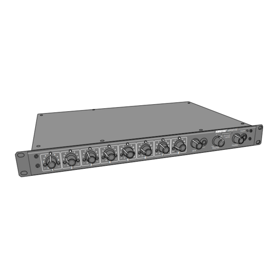
1.
Low-Cut Filter, 1–8
2.
Microphone Channel Gain Controls, 1–8
3.
Input LEDs, 1–8
4.
High-Frequency Shelving Filter, 1–8
5.
AUX Level Control
6.
Aux INPUT Jack
7.
MASTER Level Control
8.
Output Level Meter
9.
PHONES Control and Phone Jack
10. Power On LED
1998, Shure Brothers Inc.
25A1041 (RA)
The AMS8100 is an automatic microphone mixer using Shure's
patented Directional Intellimix that activates only those microphones
being addressed, minimizing poor audio caused by multiple open micro-
phones. Each AMS8100 is an eight-channel microphone mixer capable
of handling up to eight AMS microphones and two aux-level sources and
can be expanded for installations as large as 400 input channels. The
AMS8100 microphone mixer works only with Shure AMS microphones
and can be linked with Shure's SCM810 and FP410 automatic mixers.
3
4
2
13
14
12
15
16
Figure 1. AMS8100 Controls and Connectors
Service Note: Shure recommends that all service procedures be
performed by a Factory-Authorized Service Center or that the
product be returned directly to Shure Brothers Inc.
Service Manual
AMS8100 Automatic
Microphone Mixer
17
11. Power Connector and Rocker Switch
12. Microphone Logic Pin
13. DIP Switch
14. LINK IN/LINK OUT Jacks
15. OUTPUT Removable Block Connector
16. Output Level Switch (behind connector)
17. AUX/D.O/D.O Slide Switch (behind connector)
18. Input Removable Block Connectors, 1–8
19. DIRECT OUT Phone Jacks
8
9
5
6
7
18
19
Printed in U.S.A.
Products
10
Advertisement
Table of Contents

Subscribe to Our Youtube Channel
Related Manuals for Shure AMS8100


Summary of Contents for Shure AMS8100
- Page 1 AMS microphones and two aux-level sources and can be expanded for installations as large as 400 input channels. The AMS8100 microphone mixer works only with Shure AMS microphones and can be linked with Shure’s SCM810 and FP410 automatic mixers. Controls and Connectors Low-Cut Filter, 1–8 11.
-
Page 2: Circuit Description
Power Supply The AMS8100 power supply is a linear supply using discrete transis- tors for regulation. It converts varying line voltage into well regulated, multiple voltages (+15, –15) for the circuitry to use. -
Page 3: Microphone Preamps
The microphone preamps convert the current signals from the two microphone elements of an AMS microphone into voltage signals. The microphone preamps are only suitable for use with Shure AMS microphones. Conventional, balanced microphones usually have about a 150 Ω impedance and supply a small voltage for a conventional micro- phone to amplify. - Page 4 The heart of the Directional Intellimix circuitry is the direction- sensitive microphones. Each of these microphones contains two back- to-back cardioid microphone capsules. Each of these capsule’s signals is sent separately to the AMS8100 mixer via a three-conductor micro- phone cable. These microphones, in conjunction with the microphone-ratio circuitry, determine if someone is speaking within a 120 degree “acceptance angle”...
- Page 5 Previous Products Shure AMS8100 Automatic Microphone Mixer VR801 is an adjustment pot that changes the dc level at U807, pin 5, effectively changing the “acceptance angle” of the AMS microphone. This angle is factory pre-set to 120 degrees, which is 9.5 dB difference between the front and rear microphone capsules.
- Page 6 Previous Products Shure AMS8100 Automatic Microphone Mixer seconds. This time is changed by changing the DIP switch setting to 1.0 seconds, which raises the voltage at U802, pin 4. Optoisolator Turn-On Circuit When U802A’s output is pulled to ground to turn the circuit on, C818 and C817 are immediately discharged.
- Page 7 Previous Products Shure AMS8100 Automatic Microphone Mixer Logic Circuitry GATE 1 GATE 3 GATE 5 GATE 7 LOGIC GROUND MUTE 1 MUTE 3 MUTE 5 MUTE 7 O’RIDE 2 O’RIDE 4 O’RIDE 6 O’RIDE 8 MUTE 2 MUTE 4 MUTE 6...
- Page 8 Previous Products Shure AMS8100 Automatic Microphone Mixer (JFETs) to go high-impedance between their source and drain pins. Q817, C830, R8130, and R8135 again are for de-ticking. The OVERRIDE terminal for each channel works similarly to the MUTE until the output of U802C. When this point pulls low, current is pulled through D806, clamping the output of U803C to ground, and turning the channel on.
-
Page 9: Output Meter
Previous Products Shure AMS8100 Automatic Microphone Mixer Master Gain Stage and Output The master gain stage is U906B and its associated components. The master gain stage is an inverting gain stage. The output stage is U901 and its associated components. The SSM–2142 chip is an active balanced line driver. - Page 10 Previous Products Shure AMS8100 Automatic Microphone Mixer The voltage across C948 is fed to the string of comparators, U908, U909, and U912. When the outputs of these comparators are low (–15V), the individual LEDs of LED902 are off. Q929, Q931, R9189, and R9191 form a current source. This current is consumed by the comparator outputs until they go high-impedance, one by one.
-
Page 11: Disassembly And Assembly
Voltages in this equipment are hazardous to life. No user-serviceable parts are inside. Refer all servicing to qualified service personnel. The safety certifications of the AMS8100 do not apply when the operating voltage is changed from the factory setting. Front Panel Pots In this state of disassembly, most components can be accessed and the mixer can be powered and work properly. - Page 12 Previous Products Shure AMS8100 Automatic Microphone Mixer Front Panel Phone Jacks 1. Disassemble as above, through step 6. 2. Remove all nuts holding pots to the pot bracket. 3. From the bottom of the printed circuit board (pcb), remove the three screws and two standoffs holding the pot bracket to the pcb.
-
Page 13: Service Procedures
Reference Material Refer to the Service Equipment Manual for standard test equipment. Changing the Voltage The AMS8100 can be internally modified to operate from either 120 Vac or 230 Vac power. Follow these steps to change the operating voltage: 1. Disconnect the unit from the ac power source. -
Page 14: Product Specifications
Previous Products Shure AMS8100 Automatic Microphone Mixer Product Specifications After all tests are completed, the unit should perform to the following specifications. Measurement Conditions (unless otherwise specified) Line voltage: 120 Vac, 60 Hz (230 Vac, 50 Hz) Full gain: 1 kHz, one channel activated Mic 150 Ω, Line 150 Ω... - Page 15 Previous Products Shure AMS8100 Automatic Microphone Mixer Total Harmonic Distortion <0.1% at +18 dBu output level, 80 Hz to 20 kHz (through 80 Hz – 20 kHz filter; Input 1 and Master at 5; all other controls at full counterclockwise.
- Page 16 Previous Products Shure AMS8100 Automatic Microphone Mixer Notes This page intentionally left blank. 25A1041 (RA) Notes...
-
Page 17: Power Supply
Previous Products Shure AMS8100 Automatic Microphone Mixer Bench Checks Power Supply General Check to see if F901 is not blown. If it is blown, check the unit to see why it blew. If nothing can be seen, replace F901 and slowly bring the ac power up with a Variac while monitoring the supply rails. - Page 18 Previous Products Shure AMS8100 Automatic Microphone Mixer Notes This page intentionally left blank. 25A1041 (RA) Notes...
-
Page 19: Parts Designations
Previous Products Shure AMS8100 Automatic Microphone Mixer Replacement Parts and Drawings Parts Designations The following comments apply to the parts list and the schematic: The first number of the reference designator refers to its channel number. For example, R1027 refers to a channel 1 resistor, X7216 refers to a channel 7 jumper, and so forth. - Page 20 Previous Products Shure AMS8100 Automatic Microphone Mixer Table 2 Surface Mount Components Shure Part Reference Designation Description Number D100–102,105, 107,109,115,116, 200–202,205,207, 209,215,216,300– 302,305,307,309, 315,316,400–402, 405,407,409,415, 416,500–502,505, 507,509,515,516, 600–602,605,607, 609,615,616,700– 702,705,707,709, 715,716,800–802, 805,807,809,815, 816,901,902,907, 909,914–917, Diode, switching, dual 184A08 921–923,925–927 D103,104,203,...
- Page 21 Previous Products Shure AMS8100 Automatic Microphone Mixer Shure Part Reference Designation Description Number Q102–109,111– 112,114,117,202– 209,211–212,214, 217,302–309, 311–312,314,317, 402–409,411– 412,414,417, 502–509,511– 512,514,517, 602–609,611– 612,614,617, 702–709,711– 712,714,717, 802–809,811– 812,814,817, 924, Transistor 183A01 928–929,931 Q115,116,215, 216,315,316,415, 416,515,516,615, 616,715,716,815, Transistor, JFET, N channel...
- Page 22 Previous Products Shure AMS8100 Automatic Microphone Mixer Shure Part Reference Designation Description Number VR102,202,302, Potentiometer, Blue Shaft 402,502,602,702, 50 k 46A8060 VR103,203,303, 403,503,603,703, Potentiometer 100 k 20% 46A8003 803,901–903 VR104,204,304, Potentiometer, Black Shaft 404,504,604,704, 100 k 46B8060 25A1041 (RA) Replacement Parts and Drawings...
Need help?
Do you have a question about the AMS8100 and is the answer not in the manual?
Questions and answers