Table of Contents
Advertisement
Available languages
Available languages
Quick Links
DESCRIPTION
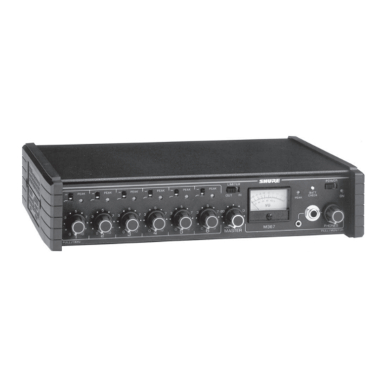
The Shure M367 is a portable, six–input, two–output (mono),
battery–powered microphone and line level mixer/preamplifier. Its
transformer–isolated design, low–noise performance, and com-
pact and rugged construction make the M367 an ideal choice for
studio and mobile broadcast, electronic news gathering (ENG),
and electronic field production (EFP) applications.
This versatile mixer can also be used for:
S digital transmission links
S digital video/audio recording media (ISDN, hard disk re-
cording, and DAT)
S sound reinforcement
The M367 comes with rubber feet, detachable power cord, and
spare power line fuse. It can be rack mounted using the optional
Model A367R rack mount kit.
FEATURES
S Six selectable mic/line inputs
S Selectable mic/line output and dedicated line output
S Transformer–balanced inputs and outputs for superior
rejection of RFI and electromagnetic hum
S Professional mechanical VU meter—LED backlighting for high
reliability, no lamp replacement
S Headphone monitoring (1/4", 3.5 mm)
S Output peak limiter with switchable threshold and bi–colored
LED indicator
S Peak indicator LED, and switchable low-cut filters on each
input
S 1/4" return monitor input
S AC power or (2) 9V battery operation
2002, Shure Incorporated
27B8511 (BC)
SIX CHANNEL MICROPHONE MIXER
Model M367 User Guide
ADDITIONAL FEATURES
S 48 V or 12 V phantom power for condenser microphones
S 1 kHz tone oscillator
S Mutes all input channels when activated
S Tone level control is on the master
S Wide–range input gain controls handle hot signal levels
without attenuators
S Customized operation via internal DIP switches, trim pots, and
optional alternate wiring
S Battery check switch and low battery warning indication
S Power-on LED
S Input expansion via mix bus jack to link M367s or other mixers
S Rugged all metal chassis with protective end caps
S Detachable ac power cord
Printed in U.S.A.
Advertisement
Table of Contents

Related Manuals for Shure M367


Summary of Contents for Shure M367
- Page 1 S Mutes all input channels when activated pact and rugged construction make the M367 an ideal choice for S Tone level control is on the master studio and mobile broadcast, electronic news gathering (ENG), and electronic field production (EFP) applications.
-
Page 2: Front Panel Controls And Indicators
FRONT PANEL CONTROLS AND INDICATORS Â Â Â Â Â Â Â Â Â Â Â M367 FRONT PANEL CONTROLS AND INDICATORS FIGURE 1 1.Input Gain Control: For best performance, adjust each Input 8.Battery Check Button: Press and hold to show battery level on Gain Control so the associated Input Peak LED illuminates red the VU meter. -
Page 3: Rear Panel Connectors And Controls
4.M267/M367 Mix Bus Level Switch: Set to M267 when connect- FIGURE 3 ing to a Shure M267, FP42, FP51, M67, or SE30. Use the M367 6.Channel Inputs: These female XLR inputs are transformer–bal- setting with another M367 or a Shure FP32A. -
Page 4: Battery Operation
AC OPERATION SETTING LEVELS Use the supplied power adapter to connect the M367 to a power 1.Set the MASTER gain knob to the full off position. outlet. 2.Activate the 1 kHz tone oscillator by setting the 1 KHZ TONE switch to ON. Adjust the MASTER gain until the VU meter needle M367: 100–120 VAC, 50/60 Hz... -
Page 5: Specifications
Power switch on; Mic/Line switches to Line; low–cut 65 dB at 100 Hz, –20 dBV input switches to flat; Limiter out; Phantom power off; Mix Bus to M367; Polarity channel 1 gain full CW; channel 2 through 6 full CCW; Master full Mic/Line In to Mic/Line Out Non–Inverting... -
Page 6: Replacement Parts
STATEMENT OF CONFORMITY interference to radio or television reception, determined by This certifies that the Shure M367E Microphone Mixer meets the turning the equipment off and on, try to correct the interference by specifications and regulations embodied in Vfg 243/1991, one or more of the following measures: amended 1992. -
Page 7: Internal Adjustments
Only qualified service technicians 5.With the M367 top cover removed, adjust the VU Level should perform these modifications. Calibration trim pot R684 with a screwdriver until the VU Meter reads 0. - Page 8 Find all pads near ribbon cable assemblies W811, W812 and W813. CHANGING OPERATOR VOLTAGE RANGE 3.Solder a new capacitor through the holes of the empty pads for The M367 and M367E can be internally modified for an alternate each channel to be modified. operating range. To increase corner frequency: M367 Operation at 220–240 Vac:...
- Page 9 (tip left, ring right, sleeve ground), and sum these signals to the monitor circuit. Note: If using a true stereo feed to drive the M367 Monitor In and another stereo device, the source impedance must be 20 Ω or less to maintain at least 40 dB separation in the stereo device.
- Page 10 CHANGING LIMITER RELEASE TIME TO ONE 6.Calculate resistor R6 value as follows: SECOND R6 = Remove resistor R741 (about 15 mm behind ribbon cable as- – sembly W813). Select a W, 1% resistor closest in value to R6 and solder it to the holes of X734.
-
Page 11: Technische Eigenschaften
S 1–kHz–Pegelton–Oszillator Design, die rauscharme Arbeitsweise sowie die kompakte und ro- S Stummschaltung aller Eingangskanäle bei Aktivierung buste Konstruktion eignet sich der M367 auf ideale Weise für Stu- S Tonpegelsteller befindet sich am Master–Pegelsteller dio– und Mobilsendungen, elektronische Berichterstattung und Außenaufnahmen. - Page 12 BEDIENELEMENTE UND ANZEIGEN AN DER FRONTSEITE Â Â Â Â Â Â Â Â Â Â Â M367 BEDIENELEMENTE UND ANZEIGEN AN DER FRONTSEITE ABBILDUNG 1 1.Eingangspegelsteller: Zur optimalen Leistung jeden Eingangs- 8.Batterieprüfknopf: Drücken und festhalten, um den Batterie- pegelsteller so einstellen, dass die zugehörige Eingangsspit- stand am VU–Meter anzuzeigen.
- Page 13 ABBILDUNG 3 4.M267/M367–Mix–Bus–Pegelschalter: Auf M267 einstellen, 6.Kanaleingänge: Diese XLR–Eingangsbuchsen sind transfor- wenn das Gerät an einen Shure M267, FP42, FP51, M67 oder mator–symmetrisch, um überragende Unterdrückung von elek- SE30 angeschlossen wird. Die Einstellung M367 für den An- tromagnetischem Brumm, HF–Störungen und anderen Störun- schluss an einen weiteren M367 oder einen Shure FP32A ver- gen zu bewirken.
-
Page 14: Dip-Schalter
WECHSELSPANNUNGSBETRIEB PEGELEINSTELLUNG Den M367 mit dem mitgelieferten Netzadapter an eine Steckdo- 1.Den MASTER–Pegelsteller auf die völlig ausgeschaltete Stellung se anschließen. drehen. 2.Den 1–kHz–Pegelton–Oszillator aktivieren, indem der 1 KHZ M367: 100–120 V AC, 50/60 Hz TONE–Schalter geschaltet wird. M367E: 220–240 V AC, 50/60 Hz MASTER–Verstärkung einstellen, bis die Nadel des VU–Meters... -
Page 15: Technische Daten
3,5 kΩ 3,5 kΩ –17 dBV 48–V–Phantomspannung: 48 V an 3,4 kΩ Wechselspannungsversorgung Ausgänge M367: 100–120 V AC, 50/60 Hz, 100 mA M367E: 220–240 V AC, 50/60 Hz, 50 mA; Stromaufnahme ohne IMPEDANZ Ausgang Signal: 25 mA Ausgang ausgelegt für Ist–Impedanz... -
Page 16: Allgemeine Informationen
— zu Masse; Kopfhörer (3,5 mm) unbelastet; Mix–Bus 930 Ω ALLGEMEINE INFORMATIONEN (M367–Stellung) bzw. 3,5 kΩ (M267–Stellung), nicht angeschlos- Nicht ausdrücklich von Shure Inc. genehmigte Änderungen oder sen, falls nicht anderweitig angegeben; 1–kHz–Eingangssignal. Modifikationen können den Entzug der Betriebsgenehmigung für ERSATZTEILE das Gerät zur Folge haben. - Page 17 3.Den 1–kHz–Pegelton–Oszillator auf die Stellung AN schalten. INTERN VERÄNDERBARE FUNKTIONEN ÄNDERUNG DES BETRIEBSSPANNUNGSBEREICHS ACHTUNG Der M367 bzw. M367E können intern auf einen anderen Be- Nur qualifizierte Wartungstechniker soll- triebsbereich eingestellt werden. ten diese Veränderungen durchführen. Betrieb des M367 bei 220–240 V AC: Alle Veränderungen durch Lötstellen, die an der Hauptleiterplat-...
- Page 18 1.Folgende Kondensatoren in der Nähe von leeren Lötaugen aus- findig machen: Kondensa- Lö- Kanal Konden- Lö- Kanal tauge sator tauge C425 X421 C455 X451 DOPPELBUCHSENAUSGANG FÜR BANANENSTECKER C435 X431 C525 X521 ABBILDUNG 5 C445 X441 C535 X531 Diesen Adapter an den Line–Ausgang des M367 anschließen.
- Page 19 ÄNDERUNG DES ABHÖREINGANGS ZU EINEM FERNSTEUERUNG DES MASTER–PEGELSTELLERS AUX–EINGANG Hinweis: Diese Veränderung deaktiviert sowohl die Abhörfunk- tion des M367 als auch seinen Master–Pegelsteller an der Front- Hinweis: Diese Änderung deaktiviert die Abhörfunktion des seite. M367. 1.Den Widerstand R641 (in der Nähe des Abhöreingangs J863) Die Widerstände R642 und R647 (in der Nähe des Kopfhörerpo-...
- Page 20 ÄNDERUNG DER 6.Den Wert des Widerstands R6 wie folgt berechnen: BEGRENZERSCHWELLEN–VOREINSTELLUNGEN R6 = 1.Die effektiven Widerstandswerte für die gewünschten Begren- – zerschwellen aus der folgenden Tabelle auswählen. Dann die ausgewählten Widerstandswerte in das folgende Arbeitsblatt Einen –W–/1–%–Widerstand auswählen, dessen Wert am eintragen.
- Page 21 S Silencia todos los canales de entrada al activarse sistente hacen del M367 una elección ideal para tareas de estudio S Control de tonos en maestro o difusión móvil, captación electrónica de noticias (ENG) y produc- ciones electrónicas en campo (EFP).
- Page 22 CONTROLES E INDICADORES DEL PANEL DELANTERO Â Â Â Â Â Â Â Â Â Â Â M367 CONTROLES E INDICADORES DEL PANEL DELANTERO FIGURA 1 1.Control de ganancia de entrada: Para el mejor rendimiento, 8.Botón de revisión de pilas: Manténgalo pulsado para mostrar ajuste cada control de ganancia de entrada de modo que su LED el nivel de carga de las pilas en el medidor de VU.
- Page 23 M267, FP42, FP51, M67 ó SE30 de Shure. Utilice la po- están balanceadas por transformador para ofrecer un rechazo sición M367 cuando se conecta esta unidad a otro M367 ó a un superior de los zumbidos e interferencias de radiofrecuencias o modelo FP32A de Shure.
- Page 24 VIDA UTIL DE LA PILA (Letra negrita = ajuste en fábrica.) Con dos pilas alcalinas frescas de 9 voltios, el M367 funciona por aproximadamente ocho horas. Algunas funciones del mezclador acortan la vida útil de las pilas, como se ilustra en la tabla siguiente.
-
Page 25: Especificaciones
Relación de rechazo en modo común Phantom desconectada; bus de mezcla a M367; ganancia de canal 65 dB con entrada de 100 Hz, –20 dBV 1 completamente en sentido horario; ganancia de canales 2 al 6... -
Page 26: Accesorios Opcionales
(3,5 mm) sin carga; bus de mezcla de 930 Ω finidos en la Parte 15 de las normas de la FCC y establecidos en (posición de M367) ó 3,5 kΩ (posición de M267), no conectado sal- los Reglamentos de Interferencias de Radio del Departamento Ca- vo indicación contraria;... - Page 27 U602) en la tarjeta de circuitos principal y retírela. Ubique las 5.Vuelva a armar el M367 invirtiendo el orden de los pasos anterio- zonas terminales desocupadas X621 (cerca de la resistencia R621). Suelde una resistencia de 430 Ω, res, colocando los tornillos Phillips en el orden indicado en las W a través de los agu-...
- Page 28 Condensa- Zona Canal Conden- Zona Canal termi- sador termi- C425 X421 C455 X451 SALIDA CON DOS JACKS TIPO BANANA C435 X431 C525 X521 FIGURA 5 C445 X441 C535 X531 Conecte este adaptador a la salida de línea del M367.
- Page 29 CONTROL REMOTO DE GANANCIA MAESTRA AUXILIAR Nota: Esta modificación desactiva la función de monitor del M367 y su control de ganancia maestra en el panel delantero. Nota: Esta modificación desactiva la función de monitor del M367. 1.Retire la resistencia R641 (cerca del jack de entrada de monitor J863).
- Page 30 CAMBIO DE UMBRALES PREFIJADOS DEL 6.Calcule el valor de la resistencia R6 de la manera siguiente: LIMITADOR R6 = 1.Seleccione los valores equivalentes de resistencia para los um- – brales deseados del limitador, usando la tabla siguiente. Des- pués llene la hoja de trabajo siguiente con las resistencias selec- cionadas.
- Page 31 SHURE Incorporated Web Address: http://www.shure.com 222 Hartrey Avenue, Evanston, IL 60202–3696, U.S.A. Phone: 847-866–2200 Fax: 847-866-2279 In Europe, Phone: 49-7131-72140 Fax: 49-7131-721414 In Asia, Phone: 852-2893-4290 Fax: 852-2893-4055 Elsewhere, Phone: 847-866–2200 Fax: 847-866-2585...
Need help?
Do you have a question about the M367 and is the answer not in the manual?
Questions and answers