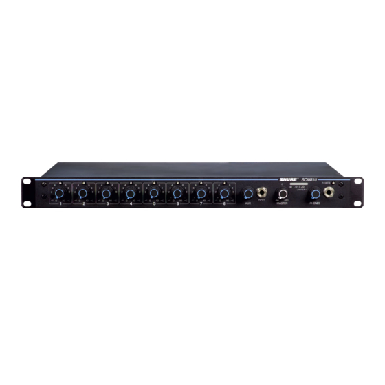
Shure SCM810 User Manual
Eight-channel microphone mixer
Hide thumbs
Also See for SCM810:
- User manual (17 pages) ,
- Manual (14 pages) ,
- Specification sheet (2 pages)
Summary of Contents for Shure SCM810
- Page 1 Model SCM810/SCM810E User Guide SCM810/SCM810E EIGHT-CHANNEL MICROPHONE MIXER 2002, Shure Incorporated Printed in U.S.A. 27C8504 (BJ)
-
Page 2: Table Of Contents
..........SCM810/E CONNECTIONS . -
Page 3: Description
SCM810/E. Multiple SCM810 mixers can be linked to other operates on 220–240 Vac power. Each mixer is supplied with a SCM810/E mixers, as well as to Shure Models FP410, SCM410, power cord, rack-mounting hardware, and a link cable. SCM800, and AMS8100 mixers. -
Page 4: Front Panel Features
14. LINK IN/OUT Jacks: Allow multiple mixers to be stacked for microphone- or line-level inputs. additional inputs. Up to 50 SCM810 mixers can be linked. 19. Input 1 - 8 MIC/PHM/LINE Switch: Located behind the re- 15. LINE OUTPUT Removable Block Connector: Active bal-... -
Page 5: Dip Switches
Hold Time: Adjusts the time an activated microphone (which is not locked on) remains on after the talker stops talking. Settings Link Global/Local: Determines whether each linked SCM810 are 0.4 seconds or 1.0 second. output contains only its own program output, or that of all linked... -
Page 6: Installation And System Setup
(center position), or line level (right switch position). TO AMP/RECORD/MIXER INPUT OR FROM AUX SOURCE (CH. 8) 3. Connect the SCM810 Line Level Output to the input of mixers, MIXER OUTPUT TO AMP/REC/MIXER INPUT EQs, amplifiers or recorders. TO LINKED SCM810 MIXERS 4. -
Page 7: Equalizer Functions
FULL CCW the frequency diminishes. The rate at which this attenuation oc- ROTATION curs is defined in decibels per octave (dB/oct). The SCM810 has a 1,000 5,000 one-pole, low-cut (high-pass) filter of 6 dB per octave. -
Page 8: Networking Multiple Mixers
Here two SCM810s are set to Local, and the resulting sound dis- tribution provides local sound reinforcement while avoiding feed- back. This is a simple “mix-minus” setup. The third SCM810 is set to Global and feeds a tape recorder, At the same time, the au- tomatic functions (Last Mic Lock-On, etc.) remain common to all... -
Page 9: Specifications
*For systems requiring other mains connectors, obtain a power cord with 20 Hz - 20 kHz filter) an IEC 320 type mating connector for connection to the SCM810, and an Output Hum and Noise (through 20 Hz to 20 kHz filter; channel appropriate plug on the other end for connection to the mains. -
Page 10: Advanced Functions
ADVANCED FUNCTIONS The SCM810’s Advanced Functions are recommended only for those who are technically knowledgeable and familiar with audio electronics. LOGIC CONNECTION SPECIFICATIONS The logic functions of the SCM810 expand the mixer’s range of Logic controls are accessed at the DB-25 multi-pin connector on installation and control options. -
Page 11: Suggested Logic Applications
SUGGESTED LOGIC APPLICATIONS This section contains suggestions on the uses of the SCM810’s Remote Channel-On Indicators logic capabilities. Note that uses of these functions are not limit- Remote indicators can be used to indicate when a talker’s micro- ed to the listed applications. The user is limited only by individual phone is on. - Page 12 NOTE: A diode across each relay coil is required to suppress in- Inhibit Function ductive voltage spikes which may damage the SCM810. See Internal Modifications. An existing sound system using 24-volt relays can be used with the SCM810 without modification if the relay coil current draw is under 500 mA.
-
Page 13: Voltage Selection
*For systems requiring other mains connectors, obtain a power cord with setting. an IEC 320 type mating connector for connection to the SCM810, and an To change the operating voltage, follow these steps. appropriate plug on the other end for connection to the mains. The sup- plied cord uses Harmonized IEC Cordage with color coding as follows: 1. -
Page 14: Internal Modifications
R1027 refers to a Channel 1 resistor, X7216 refers to a Channel 7 This section describes SCM810 modifications that can be made jumper, etc. All references to Channels 1 through 8 in the fol- using solder “jumpers”... - Page 15 1. The Direct Out jack tip is the input from the mixing console, and the ring is the output to the mixing console. 2. The SCM810 channel inputs, faders and EQ do not function. 3. NOMA does not function, channel Off-Attenuation is infinite.
- Page 16 4. Run the jumper wires to the desired remote location and solder them to an SPST toggle switch. The wires can exit the SCM810 chassis above the DIP switches. Shorting any wire to the Ground wire will set the function(s) to the corresponding switch “down”...


Need help?
Do you have a question about the SCM810 and is the answer not in the manual?
Questions and answers