Table of Contents
Advertisement
Quick Links
Advertisement
Table of Contents

Related Manuals for Seltron RT Series


Summary of Contents for Seltron RT Series
- Page 1 User Manual and Installation Instructions RT.., WT..
- Page 3 INTRODUCTION Thank you for purchasing the Seltron room thermostat. The Seltron room thermostat allows you to efficiently and economically heat or cool your rooms. With a simple user interface, you can easily set the temperature you want, adjust the operating schedule or activate any of the user functions for a comfortable temperature, saving mode or holiday mode.
-
Page 4: Table Of Contents
TABLE OF CONTENTS Room thermostat display ........................... 6 Wireless receiver display ..........................7 Description of symbols ..........................8 Overview of data ............................12 Changing the settings ..........................12 Switching on/off and selecting the operating mode ..............13 Setting the temperature ........................... 14 Setting the requested day and night temperature ..............14 Setting the temperature for frost or overheating protection ..........15 Using special functions ..........................16 Party function ............................16... - Page 5 TABLE OF CONTENTS Connection of the wireless thermostat to the receiver ...............47 Connecting wireless sensor ........................48 Connecting wireless sensor to thermostat.................48 Connecting wireless sensor to receiver ..................48 Receiver – manual operation .........................49 Technical data ..............................50 Disposal of old electrical and electronic equipment ..............51...
-
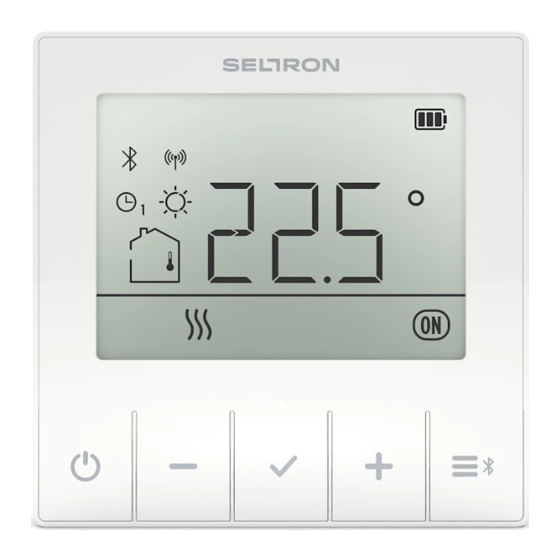
Page 6: Room Thermostat Display
ROOM THERMOSTAT DISPLAY LCD display with illumination. On/off button. Button for reducing a setting or moving backwards. Button for reviewing data and entering settings. Button for increasing a setting or moving forwards. Button for user functions and connecting to smart device. Button to connect to the receiver. -
Page 7: Wireless Receiver Display
WIRELESS RECEIVER DISPLAY LED light that shows the status of the relay output. LED light that shows the connection to the smart device. LED light that shows the connection to the thermostat. LED light that shows operation. Manual operation/connection/reset button. User Manual... -
Page 8: Description Of Symbols
DESCRIPTION OF SYMBOLS Symbols to display condition and status. Display of temperatures and other climate data in the room. Operating mode display. User Manual... - Page 9 DESCRIPTION OF SYMBOLS Event display symbols The battery is 100% charged. Locked buttons. The battery is 50% charged. Manual mode The battery is 20% charged. In the settings menu, this means that the parameter value is changed. Battery charging is required. Battery is charging.
- Page 10 DESCRIPTION OF SYMBOLS Symbols for displaying measured and requested temperatures and other information Measured outdoor Requested day temperature. temperature. Measured room Requested night temperature. temperature. Measured temperature of the Requested temperature auxiliary sensor. for frost and overheating protection. Symbols for displaying time programmes Monday Time when the Party or Eco Tuesday...
- Page 11 DESCRIPTION OF SYMBOLS Symbols for operation mode indication Turn off room heating or Party function active. cooling. Frost or overheating protection activated. Eco function active. Room heating. Holiday function active. Room cooling. Ventilation function active. Relay output active. User Manual | 11...
-
Page 12: Overview Of Data
OVERVIEW OF DATA In addition to room temperature, the room thermostat measures and displays other information about its operation. Browsing through data by pressing the button. What information can be displayed depends on the type of the thermostat and the setting of parameters from P1.10 to P1.19. With parameter P1.18, you can set the basic display to automatically display the requested number of other of data that you selected for viewing along with the measured room temperature. -
Page 13: Switching On/Off And Selecting The Operating Mode
ON/OFF AND OPERATION MODE SELECTION By pressing the button for 1 second, you can turn room thermostat opearation on or off. 1 sec. Off. Frost or overheating Room heating is active. protection remains active Hold the button for 10 seconds to switch between heating and cooling mode. The operation mode can only be selected if the thermostat operation is switched off. -
Page 14: Setting The Temperature
SETTING THE TEMPERATURE Setting the requested day and night temperature By pressing the button, you activate the requested temperature setting. The current active temperature (day or night) starts flashing. With further presses of the button, you change the value of the requested temperature. -
Page 15: Setting The Temperature For Frost Or Overheating Protection
SETTING THE TEMPERATURE Setting the temperature for frost protection Even when the room thermostat is switched off , it activates heating and adjusts the temperature to the value set for frost protection, or activates cooling and maintains the temperature at 34 °C. The temperature for frost protection can be set when the controller is switched off. -
Page 16: Using Special Functions
USING SPECIAL FUNCTIONS Party function Party function enables to switched on operation according to the requested comfort temperature at any time. By pressing the button, you select the requested function and confirm it with the button. By pressing the buttons, you can change the requested comfort temperature. -
Page 17: Eco Function
USING SPECIAL FUNCTIONS Eco function The Eco function enables you to switch on operations at the requested saving temperature at any time. By pressing the button, you select the requested function and confirm it with the button. By pressing the buttons, you can change the requested saving temperature. -
Page 18: Holiday Function
USING SPECIAL FUNCTIONS Holiday function The Holiday function allows you to activate heating with the requested saving temperature until a specific date at any time. By pressing the button, you select the requested function and confirm it with the button. By pressing the buttons, you can change the requested saving... -
Page 19: Ventilation Function
USING SPECIAL FUNCTIONS Ventilation function The Ventilation function disables the influence of the measured room temperature for a certain duration. By pressing the button, you select the requested function and confirm it with the button. Buttons are used to set the time when the Ventilation function should stop. -
Page 20: Settings Menu
SETTINGS MENU You enter the menu by pressing the button for 2 seconds. All data and settings are sorted into seven submenus: program timer – the first time program, program timer – the second time program, program timer – time and date settings, room thermostat data, user settings –... -
Page 21: Additional And Service Settings
ADDITIONAL AND SERVICE SETTINGS Basic display Selecting the submenu Enter menu 2 sec. Exit menu User Manual | 21... -
Page 22: Program Timer
PROGRAM TIMER The program timer determines the time intervals of operation with the requested daily temperature. The remaining time is the operation with the requested night temperature. The programme timer enables two independent time programmes that can be changed at will. The first time programme is marked as CH1 and the second as CH2. Each time programme allows you to set up to 21 time intervals of heating with the requested day temperature. - Page 23 PROGRAM TIMER You can enter the program timer by using the menu. To enter the menu, press and hold for 2 seconds. Select the requested time programme CH1 or CH2 with the buttons. Enter the submenu of the time programme CH1 or CH2 by pressing the button.
-
Page 24: Preset Time Programmes
PROGRAM TIMER Preset time programmes The factory (default) settings are shown in the table. Time programme Requested day temperature interval MON - FRI 06:00 - 22:00 CH1 * SAT - SUN 07:00 - 23:00 05:00 - 07:30 MON - FRI 13:30 - 22:00 SAT - SUN 07:00 - 23:00... -
Page 25: Setting The Time And Date
TIME AND DATE SETTINGS To set the correct time and date, select for the “td” submenu as described in the “Settings menu” section. By pressing the button, you enter the submenu, and by pressing the buttons, you find the requested td setting td.1 to td.4. Pressing button displays the setting value. -
Page 26: Room Thermostat Information
GENERAL INFORMATION ABOUT THE ROOM THERMOSTAT Submenu d1 contains data describing the thermostat type and software version, as well as the error code if present. When you enter the submenu d1, you can browse the data with the buttons. Settings menu. Setting or parameter indication. - Page 27 GENERAL INFORMATION ABOUT THE ROOM THERMOSTAT Submenu d1 contains the following information: Description ROOM THERMOSTAT TYPE rt1b = RT1B rt2b = RT2B d1.1 rt1nn = RT1M rt2nn = RT2M uut1b = WT1B uut1nn = WT1M uut2nn = WT2M d1.2 ROOM THERMOSTAT SOFTWARE VERSION OEM AND THERMOSTAT FAMILY d1.3 rrd = RRD...
- Page 28 SETTINGS PARAMETERS The submenus P1, P2, and S1 contain parameters for operation settings. When entering submenu P1, P2, or S1, you can browse through the parameters with . Confirm the setting of the selected parameter by pressing the button again. To exit the parameter and move to the next parameter press Press the button to change the parameter setting –...
-
Page 29: Operating Settings P1
SETTINGS PARAMETERS Operation settings P1 Submenu P1 contains the following settings or operating parameters: Description Range TEMPERATURE DISPLAY ROUND-OFF 1 ÷ 4 (3) With this setting, you can determine to what value the measured temperature display will be rounded off. P1.1 1 - 0.1 °C 2 - 0.2 °C... - Page 30 SETTINGS PARAMETERS Description Range ACTIVE SCREEN ILLUMINATION 0 ÷ 100%, (60) on RT1B, RT2B, The setting determines the brightness of the P1.6 screen when it is active. (%) and WT1B (80) on RT1M, RT2M, WT1M, and WT2M SOUND 0 ÷ 2 (2) This setting determines when sound is activated.
- Page 31 SETTINGS PARAMETERS Description Range FIRST DISPLAY IN INFO LINE 0 ÷ 8 (2) This setting determines which data will be displayed first in the info line. 0 – disabled 1 – room temperature 2 – time P1.11 3 – date 4 –...
- Page 32 SETTINGS PARAMETERS Description Range SEVENTH DISPLAY IN INFO LINE 0 ÷ 8 (0) This setting determines which data will be P1.17 displayed seventh in the info bar. Setting range is identical to parameter P1.11. NUMBER OF DATA ON BASIC DISPLAY 1 ÷...
-
Page 33: Settings Parameters
SETTINGS PARAMETERS P2 operation settings Submenu P2 contains the following settings or operating parameters: Description Range OPERATING MODE 1 ÷ 3 (3) The setting determines the operating mode of the room thermostat. 1 - Hysteresis operation, see P2.3. The operation is described in detail in the chapter "Hysteresis (H)". - Page 34 SETTINGS PARAMETERS Description Range TIME DELAY OF R1 RELAY OUTPUT REACTIVATION 0 ÷ 30 min (0) The setting determines the delay time after which the P2.14 R1 relay output can be switched on again. This setting has an effect in hysteresis mode (P2.2 = 1). (minutes) LIMITING THE MINIMUM ON/OFF TIME OF 0 ÷...
-
Page 35: Service Settings S1
SETTINGS PARAMETERS Service settings S1 Access to submenu S1 is factory-locked and hidden. To enter submenu S1, proceed as follows: locate submenu P2 in the menu, then press and hold the button for 10 seconds. View and change settings: When entering the S1 submenu, you can scroll through the settings or parameters with the buttons . - Page 36 SETTINGS PARAMETERS Description Range EXTERNAL SWITCH AT THERMOSTAT AUX INPUT 0 ÷ 4 (0) This setting determines the purpose of using the external switch at the AUX input of the thermostat. 0 – disabled S1.5 1 – activating day temperature 2 –...
- Page 37 SETTINGS PARAMETERS Description Range CALIBRATION OF WIRELESS THERMOSTAT SENSOR -5.0 ÷ 5.0 °C (0.0) This setting determines the correction of the measured S1.11 temp. of the wireless thermostat sensor. (°C) CALIBRATION OF AUXILIARY SENSOR AT -5.0 ÷ 5.0 °C (0.0) RECEIVER AUX INPUT S1.12 This setting determines the correction of the...
- Page 38 SETTINGS PARAMETERS Description Range MAXIMUM SETTING OF REQUESTED TEMPERATURE 4 ÷ 40 °C (30) S1.19 The setting determines the maximum possible setting of the requested room temperature. LOCKING THE TIME PROGRAMME 0÷ 1 (1) This setting restricts access to the time programme S1.20 setup.
-
Page 39: Description Of Operation
DESCRIPTION OF OPERATION The room thermostat provides several modes of operation. This allows us to optimally adjust its performance for different cases of installation and use. Hysteresis (H) Select by setting the parameter P2.2 = 1. Use parameter P2.3 to set the hysteresis width. With parameter P2.14 we can set the minimum delay time for relay output restart. -
Page 40: Proportional Operation (P)
DESCRIPTION OF OPERATION Proportional operation (P) Select by setting the parameter P2.2 = 2. With parameter P2.4 we set the time interval (ED constant) of modulation of operation. With parameter P2.5 we set the size of the proportional (P) control zone. Proportional, integral operation (PI) This is the default mode of operation, P2.2 = 3. -
Page 41: Locking Buttons
LOCKING BUTTONS Locking the buttons restricts or disables unwanted settings or feature activation. The buttons are locked and unlocked by pressing the button for 10 seconds. Which buttons are locked is set with parameter S1.17. Locked buttons are indicated by the symbol in the basic display. -
Page 42: Operating The Thermostat With Smart Device
OPERATING THE THERMOSTAT WITH SMART DEVICE The thermostat can also be operated using an app on the smart device. You can download the Clausius BT app from Google Play for Android smart devices and from iStore for iOS devices. To operate the thermostat, it is necessary to pair the thermostat with the application on the smart device. -
Page 43: Malfunction
MALFUNCTION When the symbol appears on the screen, the thermostat has malfunctioned. In parameter d1.7, you can read the code or cause of the malfunction. A description of the malfunction, how the thermostat works in this case, and how to deal with the malfunction is shown in the table. - Page 44 MALFUNCTION Malfunction Description of the malfunction, emergency operation, and code troubleshooting instructions The auxiliary temperature sensor connected to the base of the thermostat is interrupted or short-circuited. Failure of the auxiliary Emergency operation sensor If the room temperature sensor is selected with parameter connected to S1.3 and no other room temperature sensor is available, the the base of the...
- Page 45 MALFUNCTION Malfunction Description of the malfunction, emergency operation, and code troubleshooting instructions The internal room temperature compensation sensor on the thermostat is interrupted or short-circuited. Internal compensation Emergency operation sensor failure The thermostat compensation algorithm shuts down. Instructions for eliminating the malfunction The thermostat must be sent in for repair.
- Page 46 MALFUNCTION Malfunction Description of the malfunction, emergency operation, and code troubleshooting instructions The auxiliary temperature sensor connected to the receiver is interrupted or short-circuited. Error of Emergency operation auxiliary If the room temperature sensor is selected with parameter sensor S1.6 and no other room temperature sensor is available, the connected to thermostat switches off the operation of the relay output.
-
Page 47: Connection Of The Wireless Thermostat To The Receiver
CONNECTION OF THE WIRELESS THERMOSTAT TO THE RECEIVER The thermostat and receiver are already connected by default and do not need to be connected again. However, in case of malfunction and replacement, the thermostat and receiver must be reconnected. Within 30 seconds after switching on the power supply, activate the connection with the thermostat by pressing the button on the receiver for 2 seconds. -
Page 48: Connecting Wireless Sensor
CONNECTING THE WIRELESS SENSOR An auxiliary wireless sensor can be connected to the thermostat and receiver. Connecting a wireless sensor to the thermostat Press the button on the wireless sensor. Then press the wireless pairing button the room thermostat. The symbol starts flashing on the display. -
Page 49: Receiver - Manual Operation
RECEIVER – MANUAL OPERATION In the event of a thermostat failure or a non-functional connection between the thermostat and the receiver, activate the manual mode of operation by briefly pressing the button on the receiver after 30 seconds have elapsed since the power was turned on. -
Page 50: Technical Data
TECHNICAL DATA RT1B RT1M RT2M WT1B WT1M WT2M Illuminated display Temperature sensors Murata NTC (10 kOhm) Auxiliary temperature Murata NTC (10 kOhm) sensor (AUX) Humidity sensor optional, 10% ÷ 90% Rh Battery Battery 230VAC, 230VAC, 230VAC, 230VAC, Power supply LiPo 3.7V, LiPo 3.7V, 50Hz 50Hz... -
Page 51: Disposal Of Old Electrical And Electronic Equipment
DISPOSAL OF OLD ELECTRICAL AND ELECTRONIC EQUIPMENT Disposal of old electrical and electronic equipment (valid for EU member states and other European countries with organised separate waste collection). This symbol on the product or packaging marks that it should not be discarded as household waste. - Page 52 No part of this document may be reprinted, reproduced, translated or copied to a system used for storage and retrieval of data by electronic or mechanical means, photocopied, recorded or stored, without the written permission of Seltron. We reserve the right to make changes or errors. 52 |...
- Page 53 User Manual | 53...
- Page 54 54 | User Manual...
- Page 56 Seltron d.o.o. Tržaška cesta 85 A SL-2000 Maribor Slovenia T: +386 (0) 2 671 96 00 F: +386 (0) 2 671 96 66 info@seltron.eu www.seltron.eu 01MC060823 ©2022 We reserve the right to make errors and changes without prior notice.
Need help?
Do you have a question about the RT Series and is the answer not in the manual?
Questions and answers