
Related Manuals for Seltron RCD3


Summary of Contents for Seltron RCD3
- Page 1 Room unit RCD3, RCD4, RCD4 Premium RCD3 – Wired or wireless room unit RCD4 – Wireless room unit RCD4 Premium – Wired room unit with air quality sensor Instructions for use and setup...
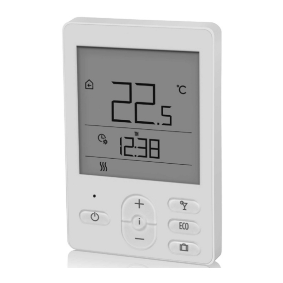
- Page 3 ENGLISH ROOM UNIT RCD3 APPEARANCE 1 – Illuminated display. 2 – Button for increasing a setting or moving forward. 3 – Light sensor. 4 – Button for reviewing data and entering the setup. 5 – Button for reducing a setting or moving backwards.
- Page 4 ROOM UNIT RCD4 APPEARANCE 1 – Illuminated display. 2 – Button for increasing a setting or moving forward. 3 – Button for reviewing data and entering the setup. 4 – Light sensor. 5 – Button for turning on/off the room heating. 6 –...
- Page 5 ROOM UNIT DISPLAY event display symbols display of the measured and desired temperatures and other information display of time, day of the week, and state of time programmes operation mode display English 5...
- Page 6 DESCRIPTIONS OF SYMBOLS ON THE SCREEN Event display symbols Symbol Description Error. See section “ERROR DESCRIPTION”. Notification. See section “DESCRIPTION OF NOTIFICATIONS”. Low battery warning. Locked buttons. This symbol on the home screen means the command for remote control has been activated. Data review and implementation of settings.
- Page 7 Symbols for displaying the measured and desired temperatures and other data Symbol Description Measured room temperature. Measured external temperature. Measured supply line temperature. Measured auxiliary sensor temperature (AUX). Measured relative air humidity in the room. Desired daytime temperature. Desired nighttime temperature. Desired frost protection temperature.
- Page 8 Operation according to time programme – day interval. * Operation according to time programme – night interval. * The time when the Party or Eco function ends. The date when the Holiday function ends. * The number next to the symbol indicates if the first or the second time pro- gramme is selected.
- Page 9 INFO – REVIEW OF DATA The room unit measures and displays the room temperature in addition to other information about the microclimate in the room. Use the button to browse through data. How much and which data we can browse through is determined with the parameters P1.10 to P1.17.
- Page 10 SETTING THE DESIRED DAYTIME TEMPERATURE Press the button to activate the setup of the desired daytime temperature. Buttons change the desired temperature. Press the button to return to the home screen. Setting the desired daytime temperature is enabled only when the functions Party, Eco or Holiday are not active. SETTING THE DESIRED NIGHTTIME TEMPERATURE Press the button to activate the...
-
Page 11: Time And Date Setting
SETTING THE FROST PROTECTION TEMPERATURE Press the button to activate the setup of the desired daytime temperature. Press the button twice to move to the frost protection temperature display. By pressing the button and holding it for at least 2 seconds, the setting value starts flashing and you can change it with the buttons . -
Page 12: Party Function
PARTY FUNCTION The Party function allows for the activation of operation at the desired comfort temperature at any time. The function can be activated by pressing the button (RCD4 only). desired comfort or Party temperature time when the Party function ends Party function display Now you can change the desired comfort temperature with the buttons . -
Page 13: Eco Function
ECO FUNCTION The Eco function allows for the activation according to the desired low-energy temperature at any time. The function can be activated by pressing the ECO button (RCD4 only). desired low-energy or Eco temperature time when the Eco function ends Eco function display Now you can change the desired low-energy temperature with the buttons... -
Page 14: Holiday Function
HOLIDAY FUNCTION The Holiday function enables the activation of operation at the desired low-energy temperature up to a specific date at any time. The function can be activated by pressing the button (RCD4 only). desired low-energy temperature or Holi- day temperature date when the Holiday function ends Holiday function display Now you can change the desired low-energy temperature with the... - Page 15 PROGRAM TIMER, ADDITIONAL AND SERVICE SETTINGS Access to the program timer, additional and service settings is possible through the menu. Settings data and parameters are located in seven menu groups: CH1 – program timer – first time programme, CH2 – program timer – second time programme, t1 –...
- Page 16 PROGRAM TIMER – TIME PROGRAMME You can choose between two time programmes found in groups CH1 and CH2. Using the time programme, you can define the time intervals of operation according to the desired daytime and nighttime temperature. desired desired daytime temperature nighttime temperature Data on the screen in groups CH1 and CH2 indicate the following:...
- Page 17 Example of the time interval of the desired daytime temperature from Monday to Friday between 6am and 10pm: switch-on command switch-off command for the first for the first time interval time interval CH1 group – first time programme There are 42 switch-on/switch-off commands representing 21 time intervals of the desired daytime temperature.
- Page 18 CH2 group – second time programme There are 42 switch-on/switch-off commands representing 21 time intervals of the desired daytime temperature. Int. Description SWITCH-ON COMMAND 1 – This setting determines the day of the week and time of the switch-on command for the first time interval (switchover to heating at the desired daytime tempera- ture).
- Page 19 DATA, AND ADDITIONAL AND SERVICE SETTINGS Data on the screen in groups t1, d1, P1, P2, and S1 indicate the following: symbol for settings display of data value or setting parameter display of group name and data sequential number or parameter Move between the data or setting parameters in each group with the buttons .
- Page 20 Group – room unit data d1.1 ROOM UNIT TYPE (RCD3, RCD4, etc.) d1.2 ROOM UNIT SOFTWARE VERSION TYPE OF CONTROLLER CONNECTED TO THE ROOM UNIT d1.3 (0 – zone controller ZCE) d1.4 CONTROLLER SOFTWARE VERSION d1.5 HYDRAULIC SCHEME OF THE CONTROLLER (1–3)
- Page 21 DISPLAY BACKLIGHT OPERATION MODE 0–3 (2) This setting determines the display backlight operation mode. Available settings: 0 – No display backlight. 1 – Maximum display brightness when configuring the room unit. After the delay time, the display P1.4 backlight is reduced to the minimum value. 2 –...
- Page 22 FIRST ADDITIONAL DISPLAY 0 – no display This setting determines the order of data displayed. 1 – room temp. 2. – external temp. For browsing data, use the i button. Parameter P1.18 can also be used to automatically display a 3 –...
- Page 23 P2 group – additional settings (parameters) No. Description Range MASTER ROOM UNIT 0 – not master unit This setting determines whether the room unit is the 1 – master unit (basic master unit. settings) In setting 1, the basic settings (desired tempera- 2 –...
- Page 24 ACCESS TO ROOM UNIT SERVICE SETTINGS Access to service settings is locked in the factory settings. It is possible to access the locked parameters in the following way: when you are in the last available group of settings (P2), press the button and hold it for 10 seconds.
- Page 25 LOCKING THE SETTINGS 0 – no lock 1 – S1 S1.9 This setting limits access to parameter groups in the menu. 2 – P1, P2, and S1 LOCKING THE BUTTONS 0 – no lock This setting locks button function. The operation 1 –...
-
Page 26: Locking The Buttons
LOCKING THE BUTTONS Locking the buttons limits or disables unwanted settings or function activations. Lock the buttons by pressing the button and holding it for 10 seconds, and unlock by pressing the button and holding it for 10 seconds. Parameter S1.10 determines the extent of locking the buttons: S1.10=0 –... -
Page 27: Error Description
ERROR DESCRIPTION Room sensor error. What can I do? The room unit must be serviced. The operation will automatically be adjusted as follows: The room sensor temperature defaults to the value of the desired room temperature. Auxiliary sensor error. What can I do? Check the type and connection of the auxiliary sensor. - Page 28 Light sensor error. What can I do? The room unit must be serviced. The operation will automatically be adjusted as follows: Display backlight is activated by pressing any button, both during the day or night. Relative humidity sensor error. What can I do? The room unit must be serviced.
- Page 29 PAIRING THE ROOM UNIT WITH THE CONTROLLER ZONE The pairing process determines which zone will be affected by the room unit being paired. A room unit that has not been paired yet only displays the mea- sured room temperature. The pairing process must first be activated on the controller where the LED lights indicate which zone is currently being paired.
-
Page 30: Technical Specifications
TECHNICAL SPECIFICATIONS RCD3, RCD3, RCD4 RCD4, wired wireless Premium, wireless wired Backlit display Temperature sensor Murata NTC (10kE) type Possibility of con- necting an auxiliary temp. sensor (AUX) Light sensor Humidity sensor Air quality sensor Air pressure sensor bus communi- 2×... -
Page 31: Disposal Of Waste Electrical And Electronic Equipment
DISPOSAL OF WASTE ELECTRICAL AND ELECTRONIC EQUIPMENT Disposal of waste electrical and electronic equipment (ap- plies to EU member states and other European countries with a waste separation system). This symbol on the product or packaging indicates it should not be discarded as household waste. - Page 32 NOTES 32 English...
- Page 33 NOTES English 33...
- Page 34 Software V1.3r0 V1.3 © 2019 We reserve the rights to errors, changes and improvements without prior notice.
Need help?
Do you have a question about the RCD3 and is the answer not in the manual?
Questions and answers