Table of Contents
Advertisement
Advertisement
Table of Contents

Subscribe to Our Youtube Channel
Related Manuals for Seltron RCD1


Summary of Contents for Seltron RCD1
- Page 1 Room unit...
-
Page 3: Table Of Contents
CONTENTS Room unit RCD1 appearance ........................4 Room unit RCD2 appearance ........................5 Room unit display ............................6 Descriptions of symbols on screen ....................6 Info - overview of information ........................9 Operation mode selection (RCD2 only) .....................10 Setting the requested day and night temp., and requested domestic hot water temp. -
Page 4: Room Unit Rcd1 Appearance
ROOM UNIT RCD1 APPEARANCE Illuminated display. Button for increasing a setting or moving forwards. Light sensor. Button for reviewing data and entering settings. Button for reducing the setting or moving backwards. Instructions for use... -
Page 5: Room Unit Rcd2 Appearance
ROOM UNIT RCD2 APPEARANCE Illuminated display. Button for increasing a setting or moving forwards. Light sensor. Button for reviewing data and entering settings. Button for turning on/off room heating. Button for reducing the setting or moving backwards. Button for turning on/off the Party function. Button for turning on/off the Eco function. -
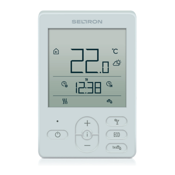
Page 6: Room Unit Display
ROOM UNIT DISPLAY Event display symbols Display of measured and requested temp. and other information Display of time, day of the week and state of time programmes Operating mode display DESCRIPTIONS OF SYMBOLS ON SCREEN EVENT DISPLAY SYMBOLS Symbol Description Warning. - Page 7 ROOM UNIT DISPLAY Symbol Description Manual intervention in controller operation. Menu for data and settings. Manual switch-off of liquid fuel boiler. Room unit address (1-first or 2-second). Sound signalling of warnings and notifications is repeated at 20:00 if warnings or notifications are still present. Parameters P1.8 and P1.9 define which events should be displayed visually and by sound.
- Page 8 ROOM UNIT DISPLAY SYMBOLS FOR DISPLAYING DAY OF THE WEEK AND STATE OF TIME PROGRAMMES Symbol Description MO - Monday, TU - Tuesday, WE - Wednesday, TH - Thursday, FR - Friday, SA - Saturday, SU - Sunday. Operation according to program interval - day temp. * Operation according to program interval - night temp.
-
Page 9: Info - Overview Of Information
ROOM UNIT DISPLAY Symbol Description Permanent switch-on of d.h.w. warming. One-time d.h.w. warming active. Anti-legionella protection active. Room heating switch-off. Frost protection activated. INFO - OVERVIEW OF INFORMATION The room unit measures and displays the room temperature in addition to other infor- mation about the microclimate in the room. -
Page 10: Operation Mode Selection (Rcd2 Only)
OPERATION MODE SELECTION (RCD2 ONLY) By pressing the button for 2 seconds we turn room heating on or off. By pressing the button for 2 seconds we turn domestic hot water warming on or off. Symbols for operation mode indication - room heating - room cooling - d. -
Page 11: Setting The Temp. For Frost Protection
OPERATION MODE SELECTION (RCD2 ONLY) SETTING THE TEMP. FOR FROST PROTECTION We can change the setting of the requested room temp. which is considered when the heating is on. When the heating is off, by pressing the button recall the display of the set temp. -
Page 12: Holiday Function (Rcd2 Only)
OPERATION MODE SELECTION (RCD2 ONLY) ECO FUNCTION (RCD2 ONLY) Eco function enables activation of heating according to the requested saving temp. at any time. Function can be activated by pressing the ECO. Requested saving or Eco temp. Time when Eco function expires Eco function display Now we can change the requested saving temp. -
Page 13: One-Time Domestic Hot Water Warming Function (Rcd2 Only)
OPERATION MODE SELECTION (RCD2 ONLY) ONE-TIME DOMESTIC HOT WATER WARMING FUNCTION (RCD2 ONLY) Function enables that we can turn one-time d.h.w. heating to the requested temp. at any time. The function is automatically turned off when domestic hot water is warm or after one hour. -
Page 14: Additional And Service Settings
ADDITIONAL AND SERVICE SETTINGS Access to additional settings is enabled through the menu. Data and parameters are located in five groups in the menu: t1 - measured and requested temperatures, d1 - data on room unit and heating controller, P1 - user settings (parameters), P2 - user settings (parameters) S1 - service settings (parameters). - Page 15 ADDITIONAL AND SERVICE SETTINGS INFORMATION GROUP T1 - TEMPERATURES Description T1 CONTROLLER SENSOR t1.1 Measured and calculated temp. for T1 sensor are displayed alternately. T2 CONTROLLER SENSOR t1.2 Measured and calculated temp. for T2 sensor are displayed alternately. T3 CONTROLLER SENSOR t1.3 Measured and calculated temp.
- Page 16 ADDITIONAL AND SERVICE SETTINGS INFORMATION GROUP D1 - GENERAL INFORMATION Description ROOM UNIT TYPE (RCD1, RCD2 etc.) d1.1 ROOM UNIT SOFTWARE VERSION d1.2 TYPE OF CONTROLLER CONNECTED TO ROOM UNIT WXD10B = 20 WXD10 = 21 WXD20 = 22 WDC10b = 32...
- Page 17 ADDITIONAL AND SERVICE SETTINGS Description Range P1.5 0 ÷ 100 % (5) MINIMUM SCREEN ILLUMINATION This setting determines minimum display illumina- tion. P1.6 0 ÷ 100 % (80) MAXIMUM SCREEN ILLUMINATION This setting determines maximum display illumina- tion. P1.7 1 ÷ 8 (6) DISPLAY CONTRAST This setting determines display contrast.
- Page 18 NUMBER OF INFORMATION ON BASIC DISPLAY 1 ÷ 9 (1) This setting determines how many information from the info line should be alternatively displayed on the basic display. * RCD1 Premium and RCD2 Premium only. PARAMETER GROUP P2 - ROOM UNIT ADDRESS Description Range P2.1...
- Page 19 ADDITIONAL AND SERVICE SETTINGS S1 PARAMETER GROUP - SERVICE PARAMETERS Description Range ROOM TEMPERATURE 0 - none 1 - built-in sensor This setting determines which sensor is used for room temp. 2 - auxiliary sensor S1.2 Info: For setting 3, median value of the installed and (AUX) auxiliary sensor is calculated for room temp.
- Page 20 ADDITIONAL AND SERVICE SETTINGS Description Range MAXIMUM SETTING OF REQUESTED TEMP. 4 ÷ 40 °C (30) This setting determines maximum possible setting of S1.12 room temp. TIME OF IGNORING ROOM TEMP. (RCD2 only) 1 ÷ 12 ur (5) Used with the »fireplace« function. Operation of fire- S1.13 place function is described in the chapter »Fireplace Function«...
-
Page 21: Locking Settings And Buttons
LOCKING SETTINGS AND BUTTONS LOCKING SETTINGS By locking settings, access to individual parameter groups is disabled. Only unlocked parameter groups are visible. Locked settings can be temporarily unlocked by pressing the button for 20 seconds, while we are in the last unlocked setting group. Parameter S1.9 determines which settings groups are locked: S1.9=0 - no lock, S1.9=1 - group S1 is locked,... -
Page 22: Factory Settings - Reset
FACTORY SETTINGS - RESET By pressing the button for 40 seconds, parameters in groups P1, P2 and S1 are restored to factory settings. Factory settings in table of parameters are marked with bold text. ERROR DESCRIPTION Error Description Room sensor error. If parameter S1.2=1, the built-in sensor contains the fault. -
Page 23: Installation And Initial Operation
INSTALLATION AND INITIAL OPERATION For installation and connection always follow the inclosed instructions. During initial operation, room unit address is set automati- cally. If one room unit is connected, it acquires address 1. If an additional room unit is connected, it acquires address 2. If two room units are connected simultaneously, address has to be confirmed or set on one of them, and the other room unit automatically acquires the remaining address. -
Page 24: Technical Data
TECHNICAL DATA RCD1 Premium / RCD1 / RCD2 RCD2 Premium Illuminated display Temp. sensor type Murata NTC (10 kE) Possibility of connect- ing an auxiliary temp. switch (AUX) Lighting sensor Humidity sensor Air quality sensor Air pressure sensor Power communication line bus... -
Page 25: Disposal Of Old Electrical And Electronic Equipment
DISPOSAL OF OLD ELECTRICAL AND ELECTRONIC EQUIPMENT Disposal of old electrical and electronic equipment (applies to EU member states and other European countries with a waste separation system). This symbol on the product or packaging marks that it should not be discarded as household waste. -
Page 26: Mounting And Electrical Connection
MOUNTING AND ELECTRICAL CONNECTION 26 | Instructions for use... - Page 27 MOUNTING AND ELECTRICAL CONNECTION 0,25 mm 0,75 mm 0,25 mm 0,5 mm 0,25 mm 0,5 mm CMP25-2 Instructions for use | 27...
- Page 28 NOTES 28 |...
- Page 29 NOTES | 29...
- Page 30 NOTES 30 |...
- Page 32 Seltron d.o.o. Tržaška cesta 85 A SL-2000 Maribor Slovenia T: +386 (0) 2 671 96 00 F: +386 (0) 2 671 96 66 info@seltron.si www.seltron.eu 01MC060777 ©2021 We reserve the right to errors, changes and improvements without prior notice.
Need help?
Do you have a question about the RCD1 and is the answer not in the manual?
Questions and answers