Advertisement
Quick Links
Advertisement

Subscribe to Our Youtube Channel
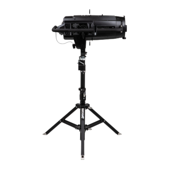
Summary of Contents for Robe ROBIN T11 MFS
- Page 1 QR code for user manual Version 1.3...
-
Page 2: Table Of Contents
Robin T11 Manual FollowSpot (MFS) handles Table of contents 1. Safety instructions ......................3 2. Parts of the Robin T11 MFS handles ................4 3. Installation........................5 4. FollowSpot mode ......................14 5. Technical Specifications ....................16 6. ChangeLog ........................16... -
Page 3: Safety Instructions
Refer servicing to qualified service personnel. Operate the ROBIN T11MFS handles only after having familiarized with their functions. Do not permit operation by persons not qualified for operating the ROBIN T11 MFS handles. Most damages are the results of unpro- fessional operation! Please use the original packaging if the ROBIN T11 MFS handles are to be transported. -
Page 4: Parts Of The Robin T11 Mfs Handles
2. Parts of the Robin T11 MFS handles A - Modified gel frame adaptor B - Modified yoke C - Side handle with fader D - Rear handle E - Spigot with locks F - Securing part with weight... -
Page 5: Installation
3. Installation The Robin T11 MFS handles have to be installed by a qualified workers on the Robin T11 fixture (Profile, PC/Fresnel) only. Important! Disconnect the Robin T11 fixture from mains before installing the Robin T11 MFS handles. Note: The MFS handles can be installed on both sides of the Robin T11 fixture - position of MFS handles depends on the orientation of the modified gel frame adaptor (A). - Page 6 4. Remove the original yoke (3) by unscrewing two tilt locks (4) with washers (5) and bolts M8 (6) and two hexagon socket screws M8x16 (7) with washers (8) and spacers (9). 5. Insert and screw the new yoke (B) by means of the same parts (4)-(9) which were used for the original yoke (3). Important! The semi-circular slot (10) in the new yoke (B) has to be oriented to the front lens of the fixture as shown on the picture below.
- Page 7 6. Unfold and adjust height of the tripod and distance of legs (11) by means of adjusting locks (12,13, 14,15, 16). Check that all locks (12, 13, 14, 15, 16) are fully tightened before placing the Robin T11 fixture on the tripod.
- Page 8 7. Install the spigot (F) to the tripod and fasten the T11 fixture on the spigot by means of the new yoke (B). As the T11 fixture is heavy, to workers should place and secure the T11 fixture on the tripod. Detailed procedure is described below.
- Page 9 7.2. Move the peg (21) up and secure its position by means of the lock (20). Secure the spigot in the tripod by means of the lock (19). 7.3 Insert the washer (22) on the pin (23). Check that locks (19, 21) are fully tightened and the peg (21) is in the upper position before placing the Robin T11 fixture on the tripod.
- Page 10 7.6. Screw the nut (25) on the pin (23). 7.7. Release the lock (20) and move the peg (21) down.
- Page 11 8. Screw the side handle (C) to the T11 fixture by means of two screws (27) and by means of two screws (26) to the gel frame adaptor (A). 9. Screw the rear handle (D) to the side handle (C). Unscrew the screw (28) and remove the cap (29).
- Page 12 10. Screw the part with weight (E) on the rear side of the T11 fixture by means of two screws with plastic heads (33). Screw the cap (29) back to the rear handle (D) by means of the screw (28). Note: If you have an older version of the T11 fixture, there are not holes with thread in the housing of the T11 fixture for two screws with plastic heads (33) of the part with weight (E) .
- Page 13 11. Connect the MFS box with cable (34) to the DMX input of the fixture.
-
Page 14: Followspot Mode
4. FollowSpot mode The T11 device can be switched to the FollowSpot mode to make easier control of the fixture with the ROBIN T11 MFS handles installed on the fixture. In the FollowSpot mode, the fixture is controlled by means of four control knobs and the fixture´s effects cannot be controlled by DMX. - Page 15 Page 4 (If Drop-in gobo and iris module is used) SGO (Static Gobo), values: OPEN, 1,2,3 RGO (Rotating Gobo), values: OPEN , IN1, IN2, RT1, RT2 Default=OPEN Default =OPEN IRS (Iris), values: OPEN, 1%-99%, CLSD R/I (Gobo Rotation/Indexing), values:STOP, R1%-R99%, Default=OPEN RMAX Default =STOP...
-
Page 16: Technical Specifications
Robin T11 Profile Robin T11 PC Robin T11 Fresnel Weight 9.2 kg Dimensions (mm) - ROBIN T11 MFS handles installed on the fixture Accessories 1 x ROBIN T11 MFS handles 1 x Drop-in manual Iris T11 (P/N 10980677) 1 x User manual... -
Page 17: Changelog
12/07/2022 Fader added 19/09/2022 Iris module added September 19, 2022 Copyright © 2022 Robe Lighting - All rights reserved Specifications are subject to change without notice. Made in CZECH REPUBLIC by ROBE LIGHTING s.r.o. Palackeho 416/20 CZ 75701 Valasske Mezirici...


Need help?
Do you have a question about the ROBIN T11 MFS and is the answer not in the manual?
Questions and answers