Table of Contents
Advertisement
Quick Links
NATURAL GAS MODELS:
PROPANE GAS MODELS:
SAFETY INFORMATION
WARNING
!
FIRE OR EXPLOSION HAZARD
Failure to follow safety warnings exactly
could result in serious injury, death, or
property damage.
- Do not store or use gasoline or other
fl ammable vapors and liquids in the vicinity of
this or any other appliance.
- WHAT TO DO IF YOU SMELL GAS:
•
Do not try to light any appliance.
•
Do not touch any electrical switch; do not
use any phone in your building.
•
Immediately call your gas supplier from a
neighbour's phone. Follow the gas
supplier's instructions.
•
If you cannot reach your gas supplier, call
the fi re department.
- Installation and service must be
performed by a qualifi ed installer, service
agency, or the supplier.
This appliance may be installed in an aftermarket,
permanently located, manufactured home (USA
only) or mobile home, where not prohibited by
local codes.
This appliance is only for use with the type of gas
indicated on the rating plate. This appliance is
not convertible for use with other gases, unless
a certifi ed kit is used.
INSTALLER:
Leave this manual with the appliance
CONSUMER:
Retain this manual for future reference
Wolf Steel Ltd., 24 Napoleon Rd., Barrie, ON, L4M 0G8 Canada / 103 Miller Drive, Crittenden, Kentucky, USA, 41030
$10.00
ADD PRODUCT CODE HERE (TRADE GOTHIC LT STD FONT)
LVX38N-1 / LVX50N-1 / LVX62N-1 / LVX74N-1 / LVX38N2-1 / LVX50N2-1 / LVX62N2-1 / LVX74N2-1
LVX38P-1 / LVX50P-1 / LVX62P-1 / LVX74P-1 / LVX38P2-1 / LVX50P2-1 / LVX62P2-1 / LVX74P2-1
INSTALLATION MANUAL
Phone 1 (866) 820-8686 • www.napoleon.com • hearth@napoleon.com
ADD MANUAL TITLE
CERTIFIED TO THE CANADIAN AND AMERICAN NATIONAL STANDARDS:
CERTIFIED TO THE CANADIAN AND AMERICAN NATIONAL STANDARDS:
CSA 2.22 AND ANSI Z21.50 FOR VENTED DECORATIVE GAS APPLIANCES
CSA 2.22 AND ANSI Z21.50 FOR VENTED DECORATIVE GAS APPLIANCES
IF INSTALLATION + OPERATION, ADD SERIAL
CSA /
INTERTEK
BARCODE LABEL ON THE OWNER'S MANUAL"
LOGO
Product Name / Code
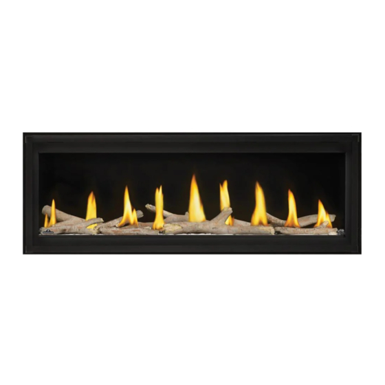
Luxuria™ Series
(MUST use title from Price Book)
ADD ____ ILLUSTRATED
ADD PRODUCT IMAGE
THIS APPLIANCE IS INSTALLED WITH
FOR INDOOR USE ONLY
FOR INDOOR USE ONLY
NUMBER LABEL HERE
PLACE BARCODE LABEL ON THE
IF SEPARATE MANUALS, ADD "PLACE
OWNER'S MANUAL
ENGLISH
FRENCH PG. 95
(LVX38-1 illustrated)
W415-2035 / C / 04.30.21
Advertisement
Table of Contents

Related Manuals for Napoleon Luxuri Series


Summary of Contents for Napoleon Luxuri Series
- Page 1 OWNER’S MANUAL BARCODE LABEL ON THE OWNER’S MANUAL” LOGO Wolf Steel Ltd., 24 Napoleon Rd., Barrie, ON, L4M 0G8 Canada / 103 Miller Drive, Crittenden, Kentucky, USA, 41030 Phone 1 (866) 820-8686 • www.napoleon.com • hearth@napoleon.com W415-2035 / C / 04.30.21...
- Page 2 safety information WARNING DANGER This appliance is hot when operated and can cause severe burns if contacted. Any changes or alterations to this appliance or its controls can be dangerous and is prohibited. HOT GLASS WILL CAUSE • Do not operate appliance before reading and BURNS.
- Page 3 safety information WARNING • Do not use a blower insert, heat exchanger insert or other accessory not approved for use with this appliance. • This appliance must not be connected to a chimney fl ue pipe serving a separate solid fuel burning appliance.
-
Page 4: Table Of Contents
table of contents electrical information general information hard wiring connection rates and effi ciencies installation checklist receptacle wiring diagram in the event of a power failure installation overview battery holder/switch installation Dynamic Heat Control™ rating plate/lighting instruction location initializing the battery holder/switch for the fi... -
Page 5: General Information
general information Installer: please fi ll out appliance checklist in the owner’s manual. 1.0 general information When the appliance is installed at elevations above 4,500ft (1372m), and in the absence of specifi c recommendations from the local authority having jurisdiction, the certifi ed high altitude input rating shall be reduced at the rate of 4% for each additional 1,000ft (305m). -
Page 6: Rates And Effi Ciencies
general information rates and effi ciencies LVX38-1 Single-Sided See-thru Appliance Type LVX38N-1 LVX38P-1 LVX38N2-1 LVX38P2-1 Fuel Type Natural Gas Propane Natural Gas Propane Altitude (FT) 0-4,500 Max. Input (BTU/HR) 31,000 26,500 31,000 26,500 Min. Input (BTU/HR) 22,000 LVX50-1 Single-Sided See-thru Appliance Type LVX50N-1 LVX50P-1... -
Page 7: Installation Checklist
general information installation checklist GAS FIREPLACE INSTALLATION CHECKLIST Customer: Date Installed: Address: Installer: Model: Dealer: Serial #: Dealer Phone #: This checklist is a reference tool only. It is not intended as a substitute for the installation instructions. Fireplace Installation IF NOT, PLEASE EXPLAIN WHY? Is the fireplace level and secured? Are the factory supplied non-combustible materials installed? -
Page 8: Installation Overview
general information general information installation overview Recommended installation steps: 1. Determine venting requirements before deciding the fi nal location of the appliance 2. Plan out appliance enclosure, framing, fronts, accessories, etc. 3. Install rough framing (refer to “rough framing” section) 4. -
Page 9: Dynamic Heat Control
general information Dynamic Heat Control™ Dynamic Heat Control™ is a system for managing the heat produced by the appliance at and around the fi re- place. The purpose of the Dynamic Heat Control™ is to move the heat away from the fi replace to allow it to cir- culate more effectively within the living space. - Page 10 general information WARNING • Always light the pilot whether for the fi rst time or if the gas supply has run out, with the glass door opened or removed. • Provide adequate clearance for servicing and operating the appliance. • Provide adequate ventilation.
-
Page 11: Rating Plate/Lighting Instruction Location
Recessed depth X” Profondeur d’encastré une face X” L’appareil doit être ventilé à l’aide de l’ensemble d’évacuation propre à Napoleon. Référez au *** Mantel X” from appliance opening *** Tablette X” de l’ouverture de l’appareil manuel d’installation pour les spécifications d’évacuation. Il est nécessaire de bien réinstaller et *** Maximum horizontal extension: *** L’extension horizontale maximale: X”. -
Page 12: Mobile Home Installation
general information mobile home installation This appliance must be installed in accordance with the manufacturer’s instructions and the Manufactured Home Construction and Safety Standard, Title 24 CFR, Part 3280, in the United States or the Mobile Home Standard, CAN/CSA Z240 MH Series, in Canada. This appliance is only for use with the type(s) of gas indicated on the rating plate. -
Page 13: Single-Sided
dimensions 2.0 dimensions single-sided Base of air collar 41 3/16" 1046mm 32 3/4" 39 11/16" 18 5/8" GLASS GUARD 832mm 1008mm 473mm 8 1/16" 7 1/16" 205mm 179mm 3 1/8" 17 11/16” 80mm 17 3/16" 1/2" (449mm) 437mm [12.7mm] Ø 8" 203mm Ø... -
Page 14: See-Thru
dimensions see-thru Base of air collar 41 3/16" 1046mm 39 11/16" 1008mm 32 3/4" 18 5/8" GLASS GUARD 832mm 473mm 8 1/16" 7 1/16" 205mm 179mm 3 1/8" 80mm 16 3/16" 1/2" 411mm Ø 8" 1/2" [12.7mm] [12.7mm] 203mm Ø 5" 127mm 8 1/16"... - Page 15 3.0 minimum venting requirements minimum venting requirements WARNING • Risk of fi re. Maintain specifi ed air space clearances to vent pipe and appliance. • The vent system must be supported every 3’(0.9m) for both vertical and horizontal runs. Use support ring assembly W010-0067 or equivalent non-combustible strapping to maintain the minimum clearance to combustibles for both vertical and horizontal runs.
-
Page 16: Minimum Venting Requirements
minimum venting requirements For optimum fl ame appearance and appliance performance, keep the vent length and number of elbows to a minimum. The air terminal must remain unobstructed at all times. Examine the air terminal at least once a year to verify that it is unobstructed and undamaged. -
Page 17: Typical Venting Installation
minimum venting requirements typical venting installation 18" (45.7cm) maximum LVX38-1 & LVX50-1: 30” (76.2cm) min LVX38-1 & LVX50-1: 62 3/4” (76.2cm) 30” LVX62-1 & LVX74N-1: 48” (121.9cm) min plus rise (76.2cm) LVX62-1 & LVX74N-1: 80 3/4” (205.1cm) minimum LVX74P-1: 58” (147,3cm) min min plus rise base of base of... - Page 18 minimum venting requirements SINGLE-SIDED OR SEE-THRU 16" (40.6cm) minimum 40 ft (12m) note: maximum A 6’ (1.83m) minimum vertical rise is 6 ft (1m) considered the minimum practical dimen- minimum sion for the specifi c appliance enclosure and a minimal building structure. However, a greater minimum vertical rise may be needed to suit the specifi...
-
Page 19: Minimum Air Terminal Location Clearances
minimum venting requirements minimum air terminal location clearances Covered balcony applications ††* = 3 feet = 2 x ACTUAL (0.9m) (4.6m) note: INSTALLATIONS Wall terminals are for illustration purposes only. Size and shapes may vary. Wall terminal CANADA U.S.A. measurements taken from the exhaust outlet, not the mounting plate. 12”... -
Page 20: Horizontal Termination
minimum venting requirements - natural gas horizontal termination LVX38-1 / LVX50-1 / LVX62-1 / LVX74-1 SINGLE-SIDED & LVX38-1 / LVX50-1 SEE-THRU (NATURAL GAS ONLY) 40’ V+H ≤ 40 ft. (For longer vent runs, a power 38 1/2’ vent is required). (462”) H ≤... - Page 21 minimum venting requirements - natural gas LVX62-1/ LVX74-1 SEE-THRU (NATURAL GAS ONLY) 40’ V+H ≤ 40 ft. (For longer vent runs, a power vent is required). 38 1/2’ (462”) H ≤ 20 ft. V + H are measured from the centre of vent elbows.
- Page 22 minimum venting requirements - natural gas 40’ (NATURAL GAS ONLY) V = V = 8 ft H = H = 10 ft Refer to appliance specific GPV/ 30’ PVA instructions for other venting configurations. 90° 20’ 90° 1-3 elbow zone 1-3 elb b o b w z w zo...
-
Page 23: Vertical Termination
minimum venting requirements - natural gas vertical termination ALL APPLIANCES (NATURAL GAS ONLY) V+H ≤ 40 ft. (For longer vent runs, 40’ a power vent is required). H ≤ 20 ft. V + H are measured from the 0 elbow zone centre of vent elbows. -
Page 24: Lvx38-1 Venting Confi Gurations
minimum venting requirements - propane LVX38-1 venting confi gurations (PROPANE ONLY) V+H ≤ 40 ft. H ≤ 10 ft. 40’ (For longer vent runs, a power vent is 38 1/2’ required). (462”) V + H are measured from the centre of vent elbows. -
Page 25: Lvx50-1 / Lvx62-1 Venting Confi Gurations
minimum venting requirements - propane LVX50-1 / LVX62-1 venting confi gurations (PROPANE ONLY) 40’ V+H ≤ 40 ft. H ≤ 4 38 ½’ (For longer vent runs, a power vent is (462”) required). V + H are measured from the centre of vent 35’... -
Page 26: Lvx74-1 Venting Confi Gurations
minimum venting requirements - propane LVX74-1 venting confi gurations (PROPANE ONLY) 40’ V+H ≤ 40 ft. H ≤ 4 38 ½’ (For longer vent runs, a power vent is (462”) required). V + H are measured from the centre of vent 35’... - Page 27 installation planning 4.0 installation planning WARNING • Do NOT cover or place any items in the Dynamic Heat Control™ air outlet. Failure to comply with these instructions will create a fi re hazard. • Ensure air fl ow within the air passage is not restricted in any way with the exception of approved venting. Read Dynamic Heat Control™...
- Page 28 installation planning If steel studs are used to facilitate a partial recess, they can only be used to a maximum depth of 3.5” (i.e. one stud). If the appliance is recessed further into the enclosure, the air fl ow will be restricted through the DHC™ system.
-
Page 29: Installation Option 1 - Open Enclosure (Enclosure Stops Short Of The Ceiling)
installation planning installation option 1 - open enclosure (enclosure stops short of the ceiling) NOT Suitable for Dynamic Heat Control™ Plus It is one option not to fi nish or close in the top of the enclosure to provide the necessary air circulation path for the Dynamic Heat Control™... -
Page 30: Installation Option 2 - Front Opening
installation planning installation option 2 - front opening Suitable for Dynamic Heat Control™ Plus Suitable for Dynamic Linear Trim Minimum air outlet opening dimensions must be followed. The opening is required to be framed no more than 1.5” below the enclosure top (see option 2 diagram) to avoid trapping heat in the upper areas and the air outlet opening centered on the appliance center. -
Page 31: Installation Option 3 - Rear Opening
installation planning installation option 3 - Rear Opening Suitable for Dynamic Heat Control™ Plus Suitable for Dynamic Linear Trim Minimum air outlet opening dimension must be followed. The opening is required to be framed no more than 1.5” below the enclosure top (see option 3 diagram) to avoid trapping heat in the upper areas and centered on the appliance center. -
Page 32: Installation Option 4 - Open Enclosure With Hard Combustible Valance
installation planning installation option 4 - open enclosure with hard combustible valance NOT Suitable for Dynamic Heat Control™ Plus Option 4 is similar to option 1 with the addition of a hard combustible valance. Minimum opening dimensions and valance dimensions must be followed (see option 4 diagram). Restricting air movement within the valance area will overheat the appliance, the enclosure, and fi... -
Page 33: Rough Framing - Before Appliance Installation
rough framing - before appliance installation 5.0 rough framing - before appliance installation note: When using optional fi nishing accessories, the framing dimensions and fi nishing materials may differ from what is outlined in the section below; refer to the leafl et instructions supplied in the accessory kit for specifi c framing and fi... -
Page 34: Minimum Framing Dimensions
rough framing - before appliance installation minimum framing dimensions 1” (2.54cm) min. 6” (15.2cm) min. Do not put objects in front of the appliance (minimum distance of 4 feet) minimum framing LVX38-1 LVX50-1 LVX62-1 LVX74-1 18” (45.7cm)** 53 13/16” (136.7cm) 65 13/16”... -
Page 35: Minimum Clearance To Combustible Enclosures
rough framing - before appliance installation 5.1.1 minimum clearance to combustible enclosures single-sided 1” [25mm] minimum all sides for sections of vertical venting. 6” [152mm] minimum (inside enclosure) When passing through a ceiling, use fi restop spacer W500-0028 3” [76mm] to top (not supplied) (outside of enclosure) 2”... - Page 36 rough framing - before appliance installation see-thru 3” [76mm] (minimum all sides for sections of horizontal 1” [25mm] venting) outside of enclosure. minimum all 6” [152mm] minimum sides for (inside enclosure) sections of vertical 3” [76mm] to top venting. (outside of enclosure) When passing through a ceiling, use fi...
- Page 37 rough framing - before appliance installation Before framing your appliance, determine vent requirements before deciding the fi nal location of the appliance. After rough framing, place the appliance in its fi nal position. single-sided Before framing the appliance, ensure to install the fi...
-
Page 38: Venting Installation
6.0 venting installation venting installation WARNING • Ensure to unpack all loose materials from inside the fi rebox prior to connecting the gas and electrical supply If your appliance is supplied with a remote, ensure the remote receiver is in the “OFF” position prior to connecting the gas and electrical supply to the appliance. - Page 39 venting installation 1. Roll the vent sleeve as shown and ensure to clip the ends together (Figure 4). 2. Ensure both ends line up and secure ends with clip and fasteners (Figure 5). Fig. 4 Fig. 5 3. Insert the vent sleeve tabs into the fi restop spacer slots then bend the tabs over to secure to the fi restop spacer along with 4 supplied fasteners (Figure 6).
-
Page 40: Horizontal Installation
venting installation horizontal installation WARNING • The fi restop assembly must be installed with the vent shield to the top. • Terminals must not be recessed into a wall or siding more than the depth of the return fl ange of the mounting plate. -
Page 41: Using Fl Exible Vent Components
venting installation using fl exible vent components WARNING • Do not allow the inner fl ex pipe to bunch up on horizontal or vertical runs and elbows. Keep it pulled tight. • Spacers are attached to the inner fl ex pipe at predetermined intervals to maintain an even air gap to the outer fl... -
Page 42: Vertical Air Terminal Installation
venting installation vertical air terminal installation WARNING • Maintain a minimum 2” (51mm) space between the air inlet base and the storm collar. note: Fastening hardware provided with appropriate roof terminal and liner kits. Fasten the roof support to the roof using 6 screws. The roof support is optional. -
Page 43: Restricting Vertical Vents
venting installation restricting vertical vents Vertical installations may display a very active fl ame. If this appearance is not desirable, the exhaust outlet may be restricted with a Wolf Steel approved restrictor kit. This kit is not recommended for short vertical vent runs. Depending on the model and/or year of your appliance, mounting holes may not exist. -
Page 44: Vent Shield Installation
venting installation vent shield installation important: For ease of installation, the front frame can be removed. The front frame must be reinstalled prior to installing the nailing tabs. note: The vent shield is telescopic and must be adjusted to shield the fi rst 30” of vertical vent always used. 1. -
Page 45: Electrical Information
venting installation 7.0 electrical information hard wiring connection It is necessary to hard wire this appliance. Permanently framing the appliance with an enclosure, requires the appliance junction box to be hard wired. This appliance must be electrically connected and grounded in accordance with local codes. In the absence of local codes, use the current CSA C22.1 Canadian Electrical Code in Canada or the ANSI/NFPA 70-1996 National Electrical Code in the United States. -
Page 46: Battery Holder/Switch Installation
electrical information battery holder/switch installation Install the battery holder/switch into a standard electrical switch box. Determine an appropriate location and install the electrical box. note: Ensure the 3 position slider switch is in the “REMOTE” position (middle). initializing the battery holder/switch for the fi rst time note: The initializing process must be completed within 10 seconds of pressing the reset / program (PRG). -
Page 47: Wiring Diagram
Napoleon’s eFIRE app controls every function of your fi replace including; on/off, fl ame height and a timer to create a schedule for your fi replace that works for you. -
Page 48: Lvx38-1/ Lvx50-1 Wiring Diagram
electrical information 7.7.1 LVX38-1/ LVX50-1 wiring diagram LAMP COMFORT W415-2035 / C / 04.30.21... -
Page 49: Lvx62-1/ Lvx74-1 Wiring Diagram
electrical information 7.7.2 LVX62-1/ LVX74-1 wiring diagram W415-2035 / C / 04.30.21... -
Page 50: Access Panel
electrical information access panel WARNING • Do not use this appliance if any part has been under water. Call a qualifi ed service technician immediately to have the appliance inspected for damage to the electrical circuit. • Risk of electrical shock or explosion. Do not wire 110V to the valve or to the appliance wall switch. Incorrect wiring will damage controls. -
Page 51: Gas Installation
electrical information 8.0 gas installation WARNING • Risk of fi re, explosion, or asphyxiation. Ensure there are no ignition sources such as sparks or open fl ames. • Support gas control when attaching gas supply pipe to prevent damaging gas line. •... -
Page 52: Operation
9.0 operation electrical information WARNING • If you do not follow these instructions exactly, a fi re or explosion may result causing property damage, personal injury, or loss of life. • If applicable, always light the pilot whether for the fi rst time or if the gas supply has run out with the glass door opened or removed. -
Page 53: Pilot-On-Demand
In order to start your pilot, turning the main burner on with the switch, remote or thermostat and then turning it off will reactivate the continuous pilot mode and reset the seven day timer. For further information, refer to www.napoleon.com/pilotondemand. W415-2035 / C / 04.30.21... -
Page 54: Nailing Tab Installation
nailing tab installation 10.0 nailing tab installation important: If the front frame was removed, it must be reinstalled prior to installing the nailing tabs. ALIGN THE NAILING TAB WITH THE HOLES ON THE APPLIANCE, REMOVE THE SCREWS FROM THE APPLIANCE. SECURE WITH THE SCREWS FROM STEP 1. -
Page 55: Framing With Dynamic Heat Control
fi nish framing - after appliance installation 11.0 fi nish framing - after appliance installation 11.1 framing with Dynamic Heat Control™ note: Appliances can be built in with combustible framing and fi nishing unless stated. There are various methods to ventilate the enclosure. Refer to “Dynamic Heat Control™” and “installation planning”... - Page 56 fi nish framing - after appliance installation single-sided recessed WARNING • Shaded components (fi nish framing) must be non-combustible materials. Ceiling note: Finish framing must be built after appliance has been placed in its fi nal position and venting con- nected.
- Page 57 fi nish framing - after appliance installation see-thru fl ush Ceiling note: Finish framing must be built after appliance has been placed in its fi nal position and venting connected. The LVX series requires a mini- mum enclosure height, as illus- trated (dimension L), measured from the bottom of the appliance.
- Page 58 fi nish framing - after appliance installation see-thru built out Drywall note: Finish framing must be built after appliance has been placed in its fi nal position and venting connected. Insulation Option 2 illustrated (appliance not shown) minimum framing LVX38-1 LVX50-1 LVX62-1 LVX74-1...
- Page 59 fi nish framing - after appliance installation wiring locations TV applications were tested with the minimum enclosure dimensions and the maximum recess permissible. This data is provided in good faith and is not a guarantee for every application and television. Care and consideration should be taken when planning these installations to ensure the temperatures around the TV meet all manufacturer’s recommended operating temperatures.
-
Page 60: Finishing
12.0 fi nishing fi nishing WARNING • Risk of fi re! • Never obstruct the front opening of the appliance. • The front of the appliance must be fi nished with any non-combustible materials such as brick, marble, granite, etc., provided that these materials do not go below the specifi ed dimension, as illustrated. •... -
Page 61: Enclosure Design
fi nishing 12.2 enclosure design Additional openings in the closure are not acceptable since the DHC™ system relies on the “chimney effect” cre- ated through the appliance and the enclosure. By adding additional air inlet(s) to an enclosure, air can bypass the appliance, which increases the operating temperature of the appliance and around the appliance opening. -
Page 62: Fi Nishing With Combustibles
fi nishing 12.3 fi nishing with combustibles With Dynamic Heat Control™, you can fi nish the appliance with any combustible materials except ap- pliances with recessed installation. Air outlet opening must be located out of reach of the user. Air outlet opening must not be restricted by furnishings or decor. - Page 63 fi nishing WARNING • Finishing material tight to the frame around the glass guard assembly frame must not project more than 4” (10cm) from the face of the glass guard (above the door and sides only). SIDE VIEW 4" 10cm 1"...
-
Page 64: Minimum Combustible Mantel Clearances
fi nishing 12.4 minimum combustible mantel clearances WARNING • Risk of fi re. Maintain all specifi ed air space clearances to combustibles. Failure to comply with these instructions may cause a fi re or cause the appliance to overheat. Ensure all clearances (i.e. back, side, top, vent, mantel, front, etc.) are clearly maintained. -
Page 65: Optional Trim Fi Nishing
fi nishing 12.5 optional trim fi nishing When the appliance is installed with the front (or rear) air outlet opening, a decorative trim kit is available to fi nish your installation. The trim kit can be painted as an accent colour or to blend in with room decor. The minimum air opening area must be maintained after the fi... -
Page 66: Glass Guard Installation / Removal
fi nishing is complete. Take precautions to protect the appliance during fi nishing. Key Components Rear view of GGA-1 • Outer glass • Horizontal tab • Napoleon logo THIS WAY UP (affi xed to intermediate glass) • GGA-1 catch • GGA-1 catch securing screws •... - Page 67 fi nishing Unpack the GGA-1 and keep packaging materials to store the GGA-1 after test fi tting. Ensure to handle the GGA-1 as shown (Fig. 1) as the fl oating intermediate glass might fall out of the assembly if handled incorrectly. For ease of installation during preliminary adjustment, remove the door trim, control cover and access panel (Fig.
- Page 68 fi nishing Fully extend the two GGA-1 slider brackets of the appliance outward (Fig. 5). Carefully hook GGA-1 onto GGA-1 slider brackets by aligning the horizontal tabs on the GGA-1 with the horizontal slots in the bottom of the GGA-1 slider brackets and moving the GGA-1 back into the GGA- 1 slider brackets (A).
- Page 69 fi nishing The GGA-1 mount bracket holes should be lined up with the screw holes of the GGA-1 slider brackets to ensure a clear line of sight (Fig. 8). It is typically necessary to raise the GGA-1 on both sides using the vertical adjustment screws.
- Page 70 fi nishing Secure GGA-1 with 1 fastener and 1 washer on top and bottom of each GGA-1 slider bracket (total of 4) holding the GGA-1 tight to the GGA-1 slider bracket surface throughout (Fig. 12). Tighten fi rmly enough to hold GGA-1 against GGA-1 slider bracket. Do not fully tighten until adjustment is complete and during fi...
- Page 71 It is REQUIRED to have the gasket touching both ends of the outer glass. Fig. 15 WARNING • Normally there is no need to adjust the position of the heat rail. Contact your authorized Napoleon dealer before attempting any adjustment of the heat rail. W415-2035 / C / 04.30.21...
- Page 72 fi nishing Check if the GGA-1 plane is straight. Adjust with horizontal adjustment screws on both ends, if necessary (Fig. 16). Move forward note: If facing material is not installed plumb and square, it may be necessary to make fi nal horizontal GGA-1 adjustments after fi...
- Page 73 fi nishing Recheck if the outer glass of the GGA-1 is touching the heat rail gasket on both ends. Check for any excessive play by lightly pulling the GGA-1 outwards. The play (rattle / movement) should be negligible in the system when the GGA-1 is held in position by the latches. If there is excessive play, the GGA-1 catches on the bottom of the GGA-1 should be adjusted forward to reduce the play to a minimal amount.
- Page 74 fi nishing To remove GGA-1 1. To open, release the latches from the GGA-1 using the release tool. Push the release tool against bottom of latch 2. Pull both sides of GGA-1 keeping it parallel to the until it disengages from GGA-1. Pull gently on GGA-1 while appliance.
-
Page 75: Fi Rebox Glass Door Installation / Removal
fi nishing 12.7 fi rebox glass door installation / removal WARNING • Do not insert fi ngers in the gap between the door and the door frame, or between the spring latches & door. there is a risk of injury due to the spring mechanism. Do not insert fi ngers in the spring door latch mechanism. FRONT - ACCESS SIDE Remove the glass guard assembly, refer to the “glass guard installation / removal”... -
Page 76: Media Tray Removal
fi nishing FIXED - SEE-THRU ONLY Remove GGA-1 from fixed side. Remove the screws securing the door to the appliance. Tilt the top of the door forward, then lift it up and out of the bottom door retainer. When re-installing the door, lift onto the bottom door retainer, tilt the top towards the appliance and secure with the previously removed screws. -
Page 77: Media Installation / Removal
fi nishing 12.9 media installation / removal WARNING • Clean the glass media prior to installation. Before applying the cleaned glass, ensure that it is dry. • If replacing, use only the replacement glass media available from your local authorized dealer / distributor. •... -
Page 78: Restricting Vertical Vents
adjustments 13.0 adjustments 13.1 restricting vertical vents Vertical installations may display a very active fl ame. If this appearance is not desirable, the vent exit in the appliance must be restricted using a restrictor vent kit. Refer to the “replacement parts” section of the owner’s manual for the appropriate kit. -
Page 79: Pilot Burner Adjustment
adjustments 13.3 pilot burner adjustment Adjust the pilot screw to provide properly sized fl ame. Turn in a clockwise direction to reduce the gas fl ow. Check Pressure Readings: Inlet pressure can be checked by turning screw (A) counter- clockwise 2 or 3 turns and then placing pressure gauge tubing over the test point. - Page 80 maintenance 14.0 maintenance WARNING • Turn off the gas and electrical power before servicing the appliance. • Appliance may be hot. Do not service until appliance has cooled. • Do not use abrasive cleaners on glass. • Do not paint the pilot assembly. This appliance and its venting system should be inspected before use and at least annually by a qualifi...
-
Page 81: Annual Maintenance
maintenance 14.1 annual maintenance WARNING • Annual maintenance should be performed by a qualifi ed service technician • The fi rebox becomes very hot during operation. Let the appliance cool completely or wear heat resistant gloves before conducting service. • Never vacuum hot embers. -
Page 82: Burner Removal
maintenance 14.3 burner removal Remove the GGA-1 and glass door, refer to the “glass guard installation / removal” & “door installation / removal” sections for details. Remove the control cover from the appliance by sliding it up and out of the clips of the front cover. Remove the media from the appliance. -
Page 83: Control Module Removal
maintenance Disconnect the fl ex connector from the valve. Remove the valve wire connections, labeling each one to aid with re-connection. Remove the screws from the valve bracket and remove the valve. Replace all components before returning the appliance to service. Check for gas leaks by brushing on a soap and water solution. -
Page 84: Led Replacement
maintenance 14.6 LED replacement This appliance comes equipped with an LED strip. If in the event the LED strip needs to be replaced, follow these instructions. Turn off all electrical supply. Remove the GGA-1 and glass door, refer to the “Glass Guard installation/removal” & “door installation/ removal”... -
Page 85: Glass / Door Replacement
maintenance 14.7 glass / door replacement WARNING • Do not use substitute materials. • Glass may be hot. Do not touch glass until cooled. • Care must be taken when removing and disposing of any broken door glass or damaged components. Be sure to vacuum up any broken glass from inside appliance before operation. -
Page 86: Replacement Parts
replacement parts 15.0 replacement parts WARNING • Failure to position the parts in accordance with this manual or failure to use only parts specifi cally approved with this appliance may result in property damage or personal injury. Contact your dealer for questions concerning prices and policies on replacement parts. Normally, all parts can be ordered through your Authorized dealer / distributor. -
Page 87: Overview
W010-4090-SER (See-thru) Door Trim W715-1158-SER W715-1159-SER W715-1162-SER W715-1163-SER Relief Door Assembly W010-1426 Door Latch Assembly W010-3554 High Limit Switch W660-0204 Napoleon Logo W385-2010 Heat Rail (w/ gasket) W010-4257-SER W010-4258-SER W010-4259-SER W010-4260-SER Media Tray W710-0104-SER W710-0107-SER W710-0099-SER W710-0098-SER Porcelain End Panel... -
Page 88: Burner Components
replacement parts 15.2 burner components Items may not appear exactly as illustrated W415-2035 / C / 04.30.21... - Page 89 replacement parts Ref. Description Part Number Stocked LVX38-1 LVX50-1 LVX62-1 LVX74-1 Flex Connector (c/w Shut-Off) W175-0217 Valve (NG) W725-0056 Valve (P) W725-0057 Control Board W190-0177 Control Board Wiring Harness W750-0276 Battery Housing W350-0655 3 Prong Light Pigtail W750-0358 LED Light Assembly W010-3661-SER W010-3652-SER W010-4079-SER...
-
Page 90: Troubleshooting
16.0 troubleshooting troubleshooting WARNING • Always light the pilot whether for the fi rst time or if the gas supply has run out, with the glass door open or removed. • Turn off gas and electrical power before servicing the appliance. •... - Page 91 troubleshooting symptom problem test solution Pilot will not light. Makes Wiring: short, loose, or damaged Verify the thermocouple/sensor is clean and the wiring is undamaged. Verify the interrupter block is not damaged or too tight. Verify noise with no spark at connections connections from pilot assembly are tight;...
- Page 92 troubleshooting symptom problem test solution Lights or blower Control module switch in Verify ON/OFF switch is in the “I” position which denotes on. won’t function (if wrong position. equipped). COM switch is unplugged. Verify “COM” switch is plugged into the front of the control module.
-
Page 93: Warranty
Napoleon neither assumes, nor authorizes any third party to assume, on its behalf, any other liabilities with respect to the sale of this product. Napoleon will not be responsible for: over- fi ring, downdrafts, spillage caused by environmental conditions such as rooftops, buildings, nearby trees, hills, mountains, inadequate vents or ventilation, excessive venting confi... - Page 94 NAPOLEON CELEBRATING OVER 40 YEARS OF HOME COMFORT PRODUCTS 7200, Route Transcanadienne, Montréal, Québec H4T 1A3 24 Napoleon Road, Barrie, Ontario, Canada L4M 0G8 214 Bayview Drive, Barrie, Ontario, Canada L4N 4Y8 103 Miller Drive, Crittenden, Kentucky, USA 41030 De Riemsdijk 22, 4004 LC Tiel, The Netherlands Phone: 1-866-820-8686 napoleon.com...
Need help?
Do you have a question about the Luxuri Series and is the answer not in the manual?
Questions and answers