Napoleon Luxuria Series Installation Manual
Hide thumbs
Also See for Luxuria Series:
- Installation manual (76 pages) ,
- Owner's manual (80 pages) ,
- Owner's manual (80 pages)
Table of Contents
Advertisement
Available languages
Available languages
NATURAL GAS MODELS:
PROPANE GAS MODELS:
SAFETY INFORMATION
WARNING
!
FIRE OR EXPLOSION HAZARD
Failure to follow safety warnings exactly
could result in serious injury, death, or
property damage.
- Do not store or use gasoline or other
fl ammable vapors and liquids in the vicinity of
this or any other appliance.
- WHAT TO DO IF YOU SMELL GAS:
•
Do not try to light any appliance.
•
Do not touch any electrical switch; do not
use any phone in your building.
•
Immediately call your gas supplier from a
neighbour's phone. Follow the gas
supplier's instructions.
•
If you cannot reach your gas supplier, call
the fi re department.
- Installation and service must be
performed by a qualifi ed installer, service
agency, or the supplier.
This appliance may be installed in an aftermarket,
permanently located, manufactured home (USA
only) or mobile home, where not prohibited by
local codes.
This appliance is only for use with the type of gas
indicated on the rating plate. This appliance is
not convertible for use with other gases, unless
a certifi ed kit is used.
INSTALLER:
Leave this manual with the appliance
CONSUMER:
Retain this manual for future reference
Wolf Steel Ltd., 24 Napoleon Rd., Barrie, ON, L4M 0G8 Canada / 103 Miller Drive, Crittenden, Kentucky, USA, 41030
Phone 1 (866) 820-8686 • www.napoleonfi replaces.com • hearth@napoleonproducts.com
$10.00
LVX38N / LVX50N / LVX62N / LVX74N / LVX38N2 / LVX50N2 / LVX62N2 / LVX74N2
ADD PRODUCT CODE HERE (TRADE GOTHIC LT STD FONT)
LVX38P / LVX50P / LVX62P / LVX38P2 / LVX50P2 / LVX62P2
INSTALLATION MANUAL
ADD MANUAL TITLE
ADD PRODUCT IMAGE
CERTIFIED TO THE CANADIAN AND AMERICAN NATIONAL STANDARDS:
CSA 2.22 AND ANSI Z21.50 FOR VENTED DECORATIVE GAS APPLIANCES
CERTIFIED TO THE CANADIAN AND AMERICAN NATIONAL STANDARDS:
CSA 2.22 AND ANSI Z21.50 FOR VENTED DECORATIVE GAS APPLIANCES
IF INSTALLATION + OPERATION, ADD SERIAL
CSA /
INTERTEK
BARCODE LABEL ON THE OWNER'S MANUAL"
LOGO
Product Name / Code
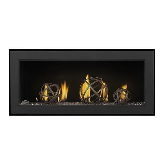
Luxuria™ Series
(MUST use title from Price Book)
ADD ____ ILLUSTRATED
THIS APPLIANCE IS INSTALLED WITH
FOR INDOOR USE ONLY
FOR INDOOR USE ONLY
NUMBER LABEL HERE
PLACE BARCODE LABEL ON THE
IF SEPARATE MANUALS, ADD "PLACE
OWNER'S MANUAL
W415-1710 / B / 08.17.18
ENGLISH
FRENCH PG. 91
(LVX38 illustrated)
Advertisement
Chapters
Table of Contents

Related Manuals for Napoleon Luxuria Series


Summary of Contents for Napoleon Luxuria Series
- Page 1 OWNER’S MANUAL BARCODE LABEL ON THE OWNER’S MANUAL” LOGO Wolf Steel Ltd., 24 Napoleon Rd., Barrie, ON, L4M 0G8 Canada / 103 Miller Drive, Crittenden, Kentucky, USA, 41030 Phone 1 (866) 820-8686 • www.napoleonfi replaces.com • hearth@napoleonproducts.com $10.00 W415-1710 / B / 08.17.18...
- Page 2 safety information WARNING DANGER • This appliance is hot when operated and can cause severe burns if contacted. • Any changes or alterations to this appliance or its controls can be dangerous and is prohibited. HOT GLASS WILL CAUSE BURNS. •...
- Page 3 safety information WARNING • Do not use a blower insert, heat exchanger insert or other accessory not approved for use with this appliance. • This appliance must not be connected to a chimney fl ue pipe serving a separate solid fuel burning appliance.
-
Page 4: Table Of Contents
table of contents general information wiring diagram eFire controller application rates and efficiencies 7.7.1 LVX38/50 wiring diagram installation overview Dynamic Heat Control™ 7.7.2 LVX62/74 wiring diagram rating plate/lighting instruction location access panel gas installation mobile home installation operation hardware list lifting handles installation/removal 10.0 nailing tab installation... -
Page 5: General Information
general information Installer: please fill out appliance checklist in the owner’s manual. 1.0 general information When the appliance is installed at elevations above 4,500ft (1372m), and in the absence of specific recommendations from the local authority having jurisdiction, the certified high altitude input rating shall be reduced at the rate of 4% for each additional 1,000ft (305m). -
Page 6: Rates And Efficiencies
general information rates and efficiencies LVX38 Single-Sided See-thru Appliance Type LVX38N LVX38P LVX38N2 LVX38P2 Fuel Type Natural Gas Propane Natural Gas Propane Altitude (FT) 0-4,500 0-4,500 0-4,500 0-4,500 Max. Input (BTU/HR) 32,000 32,000 32,000 32,000 Min. Input (BTU/HR) 22,000 25,000 23,000 25,000 40.2%... -
Page 7: Installation Overview
general information installation overview Recommended installation steps: 1. Determine venting requirements before deciding the final location of the appliance 2. Plan out appliance enclosure, framing, fronts, accessories, etc. 3. Install rough framing (refer to “rough framing” section) 4. Place the appliance in its final position 5. -
Page 8: Dynamic Heat Control
general information Dynamic Heat Control™ Dynamic Heat Control™ is a system for managing the heat produced by the appliance at and around the fire- place. The purpose of the Dynamic Heat Control™ is to move the heat away from the fireplace to allow it to cir- culate more effectively within the living space. - Page 9 general information WARNING • Always light the pilot whether for the first time or if the gas supply has run out, with the glass door opened or removed. • Provide adequate clearance for servicing and operating the appliance. • Provide adequate ventilation. •...
-
Page 10: Rating Plate/Lighting Instruction Location
«Cet appareil doit être utilisé uniquement TOP/ DESSUS 0" RECESSED DEPTH ONE SIDED/ PROFONDEUR D'ENCASTRE UNE FACE 17 15/16" THE APPLIANCE MUST BE VENTED USING THE APPROPRIATE NAPOLEON VENT KITS. SEE OWNER'S INSTALLATION MANUAL AVERTISSEMENT: NE PAS FLOOR / PLANCHER 0"... -
Page 11: Mobile Home Installation
general information mobile home installation This appliance must be installed in accordance with the manufacturer’s instructions and the Manufactured Home Construction and Safety Standard, Title 24 CFR, Part 3280, in the United States or the Mobile Home Standard, CAN/CSA Z240 MH Series, in Canada. This appliance is only for use with the type(s) of gas indicated on the rating plate. -
Page 12: Dimensions
dimensions 2.0 dimensions single-sided Base of air collar 41 3/16" 1046mm 32 3/4" 39 11/16" 18 5/8" 832mm 1008mm GLASS GUARD 473mm 8 1/16" 7 1/16" 205mm 179mm 3 1/8" 17 11/16” 80mm 17 3/16" 1/2" (449mm) 437mm [12.7mm] Ø 8" 203mm Ø... -
Page 13: See-Thru
dimensions see-thru Base of air collar 41 3/16" 1046mm 39 11/16" 1008mm 32 3/4" 18 5/8" 832mm GLASS GUARD 473mm 8 1/16" 7 1/16" 205mm 179mm 3 1/8" 80mm 16 3/16" 1/2" 411mm Ø 8" 1/2" [12.7mm] [12.7mm] 203mm Ø 5" 127mm 8 1/16"... -
Page 14: Minimum Venting Requirements
3.0 minimum venting requirements minimum venting requirements WARNING • Risk of fi re. Maintain specifi ed air space clearances to vent pipe and appliance. • The vent system must be supported every 3’(0.9m) for both vertical and horizontal runs. Use support ring assembly W010-0067 or equivalent non-combustible strapping to maintain the minimum clearance to combustibles for both vertical and horizontal runs. - Page 15 minimum venting requirements Use only Wolf Steel, Simpson Dura-Vent, Selkirk Direct Temp, American Metal Amerivent or Metal-Fab venting components. Minimum and maximum vent lengths, for both horizontal and vertical installations, clearances from vent pipes to combustibles and air terminal locations as set out in this manual apply to all vent systems and must be adhered to.
-
Page 16: Typical Venting Installation
minimum venting requirements typical venting installation 18" (45.7cm) maximum LVX38 & LVX50: 62 3/4” (76.2cm) 30” LVX38 & LVX50: 30” (76.2cm) min min plus rise (76.2cm) LVX62 & LVX74: 48” (121.9cm) min LVX62 & LVX74: 80 3/4” (205.1cm) minimum min plus rise base of base of 62 3/4"... - Page 17 minimum venting requirements SINGLE-SIDED OR SEE-THRU 16" (40.6cm) minimum note: 40 ft (12m) maximum A 6’ (1.83m) minimum vertical rise is 6 ft (1m) considered the minimum practical dimen- minimum sion for the specific appliance enclosure and a minimal building structure. However, a greater minimum vertical rise may be needed to suit the specific application con- straints or local codes and / or regulatory...
-
Page 18: Minimum Air Terminal Location Clearances
minimum venting requirements minimum air terminal location clearances Covered balcony applications ††* ≤ 15 feet = 3 feet = 2 x ACTUAL (4.6m) (0.9m) note: INSTALLATIONS Wall terminals are for illustration purposes only. Size and shapes may vary. CANADA U.S.A. 12”... -
Page 19: Horizontal Termination
minimum venting requirements - natural gas horizontal termination LVX38 / LVX50 / LVX62 / LVX74 SINGLE-SIDED & LVX38 / LVX50 SEE-THRU (NATURAL GAS ONLY) 40’ V+H ≤ 40 ft. (For longer vent runs, a power 38 1/2’ vent is required). (462”) H ≤... - Page 20 minimum venting requirements - natural gas LVX62/ LVX74 SEE-THRU (NATURAL GAS ONLY) 40’ V+H ≤ 40 ft. (For longer vent runs, a power vent is required). 38 1/2’ (462”) H ≤ 20 ft. V + H are measured from the centre of vent elbows.
- Page 21 minimum venting requirements - natural gas 40’ (NATURAL GAS ONLY) V = V = 8 ft H = H = 10 ft 30’ 90° 20’ 90° 1-3 elbow zone 15’ Base of air collar 10’ 5’ 4 3/4” (57”) 0’ 20’...
-
Page 22: Vertical Termination
minimum venting requirements - natural gas vertical termination ALL APPLIANCES (NATURAL GAS ONLY) V+H ≤ 40 ft. (For longer vent runs, 40’ a power vent is required). H ≤ 20 ft. V + H are measured from the 0 elbow zone centre of vent elbows. -
Page 23: Lvx38 Venting Configurations
minimum venting requirements - propane LVX38 venting configurations (PROPANE ONLY) V+H ≤ 40 ft. H ≤ 10 ft. 40’ (For longer vent runs, a power vent is 38 1/2’ required). (462”) V + H are measured from the centre of vent elbows. -
Page 24: Lvx50 / 62 Venting Configurations
minimum venting requirements - propane LVX50 / 62 venting configurations (PROPANE ONLY) 40’ V+H ≤ 40 ft. H ≤ 4⅜ ft. 38 ½’ (For longer vent runs, a power vent is (462”) required). V + H are measured from the centre of vent 35’... -
Page 25: Installation Planning
installation planning 4.0 installation planning WARNING • Do NOT cover or place any items in the Dynamic Heat Control™ air outlet. Failure to comply with these instructions will create a fire hazard. • Ensure air flow within the air passage is not restricted in any way with the exception of approved venting. Read Dynamic Heat Control™... - Page 26 installation planning If steel studs are used to facilitate a partial recess, they can only be used to a maximum depth of 3.5” (i.e. one stud). If the appliance is recessed further into the enclosure, the air flow will be restricted through the DHC™ system.
-
Page 27: Installation Option 1 - Open Enclosure (Enclosure Stops Short Of The Ceiling)
installation planning installation option 1 - open enclosure (enclosure stops short of the ceiling) NOT Suitable for Dynamic Heat Control™ Plus It is one option not to finish or close in the top of the enclosure to provide the necessary air circulation path for the Dynamic Heat Control™... -
Page 28: Installation Option 2 - Front Opening
installation planning installation option 2 - front opening Suitable for Dynamic Heat Control™ Plus Suitable for Dynamic Linear Trim Minimum air outlet opening dimensions must be followed. The opening is required to be framed no more than 1.5” below the enclosure top (see option 2 diagram) to avoid trapping heat in the upper areas and the air outlet opening centered on the appliance center. -
Page 29: Installation Option 3 - Rear Opening
installation planning installation option 3 - Rear Opening Suitable for Dynamic Heat Control™ Plus Suitable for Dynamic Linear Trim Minimum air outlet opening dimension must be followed. The opening is required to be framed no more than 1.5” below the enclosure top (see option 3 diagram) to avoid trapping heat in the upper areas and centered on the appliance center. -
Page 30: Installation Option 4 - Open Enclosure With Hard Combustible Valance
installation planning installation option 4 - open enclosure with hard combustible valance NOT Suitable for Dynamic Heat Control™ Plus Option 4 is similar to option 1 with the addition of a hard combustible valance. Minimum opening dimensions and valance dimensions must be followed (see option 4 diagram). Restricting air movement within the valance area will overheat the appliance, the enclosure, and finishing material. -
Page 31: Rough Framing - Before Appliance Installation
rough framing - before appliance installation 5.0 rough framing - before appliance installation note: When using optional finishing accessories, the framing dimensions and finishing materials may differ from what is outlined in the section below; refer to the leaflet instructions supplied in the accessory kit for specific framing and finishing specifications. -
Page 32: Minimum Framing Dimensions
rough framing - before appliance installation minimum framing dimensions 1” (2.54cm) min. 6” (15.2cm) min. Do not put objects in front of the appliance (minimum distance of 4 feet) minimum framing LVX38 LVX50 LVX62 LVX74 18” (45.7cm)** 18” (45.7cm)** 18” (45.7cm)** 18”... -
Page 33: Minimum Clearance To Combustible Enclosures
rough framing - before appliance installation 5.1.1 minimum clearance to combustible enclosures single-sided 1” [25mm] minimum all sides for sections of vertical venting. 6” [152mm] minimum (inside enclosure) When passing through a ceiling, use firestop spacer W500-0028 3” [76mm] to top (not supplied) (outside of enclosure) 2”... - Page 34 rough framing - before appliance installation see-thru 3” [76mm] (minimum all sides for sections of horizontal 1” [25mm] venting) outside of enclosure. minimum all 6” [152mm] minimum sides for (inside enclosure) sections of vertical 3” [76mm] to top venting. (outside of enclosure) When passing through a ceiling, use firestop spacer 2”...
- Page 35 rough framing - before appliance installation Before framing your appliance, determine vent requirements before deciding the final location of the appliance. After rough framing, place the appliance in its final position. single-sided Before framing the appliance, ensure to install the firestop first. note: The LVX series requires a minimum enclosure height, as...
-
Page 36: Venting Installation
6.0 venting installation venting installation WARNING • Ensure to unpack all loose materials from inside the fi rebox prior to connecting the gas and electrical supply • If your appliance is supplied with a remote, ensure the remote receiver is in the “OFF” position prior to connecting the gas and electrical supply to the appliance. - Page 37 venting installation 1. Roll the vent sleeve as shown and ensure to clip the ends together (Figure 4). 2. Ensure both ends line up and secure ends with clip and fasteners (Figure 5). Fig. 4 Fig. 5 3. Insert the vent sleeve tabs into the firestop spacer slots then bend the tabs over to secure to the firestop spacer along with 4 supplied fasteners (Figure 6).
-
Page 38: Horizontal Installation
venting installation horizontal installation WARNING • The fi restop assembly must be installed with the vent shield to the top. • Terminals must not be recessed into a wall or siding more than the depth of the return fl ange of the mounting plate. -
Page 39: Using Flexible Vent Components
venting installation using flexible vent components WARNING • Do not allow the inner fl ex pipe to bunch up on horizontal or vertical runs and elbows. Keep it pulled tight. • Spacers are attached to the inner fl ex pipe at predetermined intervals to maintain an even air gap to the outer fl ex pipe. -
Page 40: Vertical Air Terminal Installation
venting installation vertical air terminal installation WARNING • Maintain a minimum 2” (51mm) space between the air inlet base and the storm collar. note: Fastening hardware provided with appropriate roof terminal and liner kits. Fasten the roof support to the roof using 6 screws. The roof support is optional. -
Page 41: Restricting Vertical Vents
venting installation restricting vertical vents Vertical installations may display a very active flame. If this appearance is not desirable, the exhaust outlet may be restricted with a Wolf Steel approved restrictor kit. This kit is not recommended for short vertical vent runs. Depending on the model and/or year of your appliance, mounting holes may not exist. -
Page 42: Vent Shield Installation
venting installation vent shield installation important: For ease of installation, the front frame can be removed. The front frame must be reinstalled prior to installing the nailing tabs. note: The vent shield is telescopic and must be adjusted to shield the first 30” of vertical vent always used. 1. -
Page 43: Electrical Information
venting installation 7.0 electrical information hard wiring connection It is necessary to hard wire this appliance. Permanently framing the appliance with an enclosure, requires the appliance junction box to be hard wired. This appliance must be electrically connected and grounded in accordance with local codes. In the absence of local codes, use the current CSA C22.1 Canadian Electrical Code in Canada or the ANSI/NFPA 70-1996 National Electrical Code in the United States. -
Page 44: Battery Holder/Switch Installation
electrical information battery holder/switch installation Install the battery holder/switch into a standard electrical switch box. Determine an appropriate location and install the electrical box. note: Ensure the 3 position slider switch is in the “REMOTE” position (middle). initializing the battery holder/switch for the first time note: The initializing process must be completed within 10 seconds of pressing the reset / program (PRG). -
Page 45: Wiring Diagram
Napoleon’s eFIRE app controls every function of your fireplace including; on/off, flame height and a timer to create a schedule for your fireplace that works for you. -
Page 46: Lvx38/50 Wiring Diagram
electrical information 7.7.1 LVX38/50 wiring diagram LAMP COMFORT W415-1710 / B / 08.17.18... -
Page 47: Lvx62/74 Wiring Diagram
electrical information 7.7.2 LVX62/74 wiring diagram W415-1710 / B / 08.17.18... -
Page 48: Access Panel
electrical information access panel WARNING • Do not use this appliance if any part has been under water. Call a qualifi ed service technician immediately to have the appliance inspected for damage to the electrical circuit. • Risk of electrical shock or explosion. Do not wire 110V to the valve or to the appliance wall switch. Incorrect wiring will damage controls. -
Page 49: Gas Installation
electrical information 8.0 gas installation WARNING • Risk of fi re, explosion, or asphyxiation. Ensure there are no ignition sources such as sparks or open fl ames. • Support gas control when attaching gas supply pipe to prevent damaging gas line. •... -
Page 50: Operation
9.0 operation electrical information WARNING • If you do not follow these instructions exactly, a fi re or explosion may result causing property damage, personal injury, or loss of life. • If applicable, always light the pilot whether for the fi rst time or if the gas supply has run out with the glass door opened or removed. -
Page 51: Nailing Tab Installation
nailing tab installation 10.0 nailing tab installation important: If the front frame was removed, it must be reinstalled prior to installing the nailing tabs. ALIGN THE NAILING TAB WITH THE HOLES ON THE APPLIANCE, REMOVE THE SCREWS FROM THE APPLIANCE. SECURE WITH THE SCREWS FROM STEP 1. -
Page 52: Finish Framing - After Appliance Installation
finish framing - after appliance installation 11.0 finish framing - after appliance installation 11.1 framing with Dynamic Heat Control™ note: Appliances can be built in with combustible framing and finishing unless stated. There are various methods to ventilate the enclosure. Refer to “Dynamic Heat Control™” and “installation planning”... - Page 53 finish framing - after appliance installation single-sided recessed WARNING • Shaded components (finish framing) must be non-combustible materials. Ceiling note: Finish framing must be built after appliance has been placed in its final position and venting con- nected. This configuration also re- quires recess area to use non-combustible facing due to close proximity to vent.
- Page 54 finish framing - after appliance installation see-thru flush Ceiling note: Finish framing must be built after appliance has been placed in its final position and venting connected. The LVX series requires a mini- mum enclosure height, as illus- trated (dimension L), measured from the bottom of the appliance.
- Page 55 finish framing - after appliance installation see-thru built out Drywall note: Finish framing must be built after appliance has been placed in its final position and venting connected. Insulation Option 2 illustrated (appliance not shown) minimum framing LVX38 LVX50 LVX62 LVX74 E*** 16 3/16”...
-
Page 56: Finishing
12.0 finishing finishing WARNING • Risk of fire! • Never obstruct the front opening of the appliance. • The front of the appliance must be finished with any non-combustible materials such as brick, marble, granite, etc., provided that these materials do not go below the specified dimension, as illustrated. •... -
Page 57: Enclosure Design
finishing 12.2 enclosure design Additional openings in the closure are not acceptable since the DHC™ system relies on the “chimney effect” cre- ated through the appliance and the enclosure. By adding additional air inlet(s) to an enclosure, air can bypass the appliance, which increases the operating temperature of the appliance and around the appliance opening. -
Page 58: Finishing With Combustibles
finishing 12.3 finishing with combustibles With Dynamic Heat Control™, you can finish the appliance with any combustible materials except ap- pliances with recessed installation. Air outlet opening must be located out of reach of the user. Air outlet opening must not be restricted by furnishings or decor. - Page 59 finishing WARNING • Finishing material tight to the frame around the glass guard assembly frame must not project more than 4” (10cm) from the face of the glass guard (above the door and sides only). SIDE VIEW 4" 10cm 1" 25mm 2"...
-
Page 60: Minimum Combustible Mantel Clearances
finishing 12.4 minimum combustible mantel clearances WARNING • Risk of fire. Maintain all specified air space clearances to combustibles. Failure to comply with these instructions may cause a fire or cause the appliance to overheat. Ensure all clearances (i.e. back, side, top, vent, mantel, front, etc.) are clearly maintained. -
Page 61: Optional Trim Finishing
finishing 12.5 optional trim finishing When the appliance is installed with the front (or rear) air outlet opening, a decorative trim kit is available to finish your installation. The trim kit can be painted as an accent colour or to blend in with room decor. The minimum air opening area must be maintained after the finishing material has been installed. -
Page 62: Glass Guard Installation / Removal
GGA is removed after preliminary adjustment and stored safely in the original packaging whilst finishing is complete. Take precautions to protect the appliance during finishing. Key Components Rear view of GGA • Outer glass • Horizontal tab • Napoleon logo THIS WAY UP (affixed to intermediate glass) • GGA catch • GGA catch securing screws •... - Page 63 finishing Unpack the GGA and keep packaging materials to store the GGA after test fitting. Ensure to handle the GGA as shown (Fig. 1) as the floating intermediate glass might fall out of the assembly if handled incorrectly. For ease of installation during preliminary adjustment, remove the door trim, control cover and access panel (Fig.
- Page 64 finishing Fully extend the two GGA slider brackets of the appliance outward (Fig. 5). Carefully hook GGA onto GGA slider brackets by aligning the horizontal tabs on the GGA with the horizontal slots in the bottom of the GGA slider brackets and moving the GGA back into the GGA slider brackets (A).
- Page 65 finishing The GGA mount bracket holes should be lined up with the screw holes of the GGA slider brackets to ensure a clear line of sight (Fig. 8). It is typically necessary to raise the GGA on both sides using the vertical adjustment screws.
- Page 66 finishing Secure GGA with 1 fastener and 1 washer on top and bottom of each GGA slider bracket (total of 4) holding the GGA tight to the GGA slider bracket surface throughout (Fig. 12). Tighten firmly enough to hold GGA against GGA slider bracket. Do not fully tighten until adjustment is complete and during final GGA installation.
- Page 67 It is REQUIRED to have the gasket touching both ends of the outer glass. Fig. 15 WARNING • Normally there is no need to adjust the position of the heat rail. Contact your authorized Napoleon dealer before attempting any adjustment of the heat rail. W415-1710 / B / 08.17.18...
- Page 68 finishing Check if the GGA plane is straight. Adjust with horizontal adjustment screws on both ends, if necessary (Fig. 16). Move forward note: If facing material is not installed plumb and square, it may be necessary to make final horizontal GGA adjustments after finishing.
- Page 69 finishing Recheck if the outer glass of the GGA is touching the heat rail gasket on both ends. Check for any excessive play by lightly pulling the GGA outwards. The play (rattle / movement) should be negligible in the system when the GGA is held in position by the latches. If there is excessive play, the GGA catches on the bottom of the GGA should be adjusted forward to reduce the play to a minimal amount.
- Page 70 finishing To remove GGA 1. To open, release the latches from the GGA using the release tool. Push the release tool against bottom of latch until it 2. Pull both sides of GGA keeping it parallel to the disengages from GGA. Pull gently on GGA while releasing appliance.
-
Page 71: Firebox Glass Door Installation / Removal
finishing 12.7 firebox glass door installation / removal WARNING • Do not insert fingers in the gap between the door and the door frame, or between the spring latches & door. there is a risk of injury due to the spring mechanism. Do not insert fingers in the spring door latch mechanism. FRONT - ACCESS SIDE Remove the glass guard assembly, refer to the “glass guard installation / removal”... -
Page 72: Media Tray Removal
finishing FIXED - SEE-THRU ONLY Remove GGA from fixed side. Remove the screws securing the door to the appliance. Tilt the top of the door forward, then lift it up and out of the bottom door retainer. When re-installing the door, lift onto the bottom door retainer, tilt the top towards the appliance and secure with the previously removed screws. -
Page 73: Glass Media Installation / Removal
finishing 12.10 glass media installation / removal WARNING • Clean the glass media prior to installation. Before applying the cleaned glass, ensure that it is dry. • If replacing, use only the replacement glass media available from your local authorized dealer / distributor. •... -
Page 74: Adjustments
adjustments 13.0 adjustments 13.1 restricting vertical vents Vertical installations may display a very active flame. If this appearance is not desirable, the vent exit in the appliance must be restricted using a restrictor vent kit. Refer to the “replacement parts” section of the owner’s manual for the appropriate kit. -
Page 75: Pilot Burner Adjustment
adjustments 13.3 pilot burner adjustment Adjust the pilot screw to provide properly sized fl ame. Turn in a clockwise direction to reduce the gas fl ow. Check Pressure Readings: Inlet pressure can be checked by turning screw (A) counter- clockwise 2 or 3 turns and then placing pressure gauge tubing over the test point. -
Page 76: Maintenance
maintenance 14.0 maintenance WARNING • Turn off the gas and electrical power before servicing the appliance. • Appliance may be hot. Do not service until appliance has cooled. • Do not use abrasive cleaners on glass. • Do not paint the pilot assembly. This appliance and its venting system should be inspected before use and at least annually by a qualifi ed service person. -
Page 77: Annual Maintenance
maintenance 14.1 annual maintenance WARNING • Annual maintenance should be performed by a qualifi ed service technician • The fi rebox becomes very hot during operation. Let the appliance cool completely or wear heat resistant gloves before conducting service. • Never vacuum hot embers. -
Page 78: Burner Removal
maintenance 14.3 burner removal Remove the GGA and glass door, refer to the “glass guard installation / removal” & “door installation / removal” sections for details. Remove the control cover from the appliance by sliding it up and out of the clips of the front cover. Remove the media from the appliance. -
Page 79: Control Module Removal
maintenance Disconnect the flex connector from the valve. Remove the valve wire connections, labeling each one to aid with re-connection. Remove the screws from the valve bracket and remove the valve. Replace all components before returning the appliance to service. Check for gas leaks by brushing on a soap and water solution. -
Page 80: Led Replacement
maintenance 14.6 LED replacement This appliance comes equipped with an LED strip. If in the event the LED strip needs to be replaced, follow these instructions. Turn off all electrical supply. Remove the GGA and glass door, refer to the “Glass Guard installation/removal” & “door installation/ removal”... -
Page 81: Glass / Door Replacement
maintenance 14.7 glass / door replacement WARNING • Do not use substitute materials. • Glass may be hot. Do not touch glass until cooled. • Care must be taken when removing and disposing of any broken door glass or damaged components. Be sure to vacuum up any broken glass from inside appliance before operation. -
Page 82: Replacements
replacement parts 15.0 replacement parts WARNING • Failure to position the parts in accordance with this manual or failure to use only parts specifi cally approved with this appliance may result in property damage or personal injury. Contact your dealer for questions concerning prices and policies on replacement parts. Normally, all parts can be ordered through your Authorized dealer / distributor. -
Page 83: Overview
Relief Door Assembly W010-1426 W010-1426 W010-1426 Door Latch Assembly W010-3554 W010-3554 W010-3554 W010-3554 High Limit Switch W660-0204 W660-0204 W660-0204 W660-0204 Napoleon Logo W385-2010 W385-2010 W385-2010 W385-2010 Heat Rail (w/ gasket) W010-4257-SER W010-4258-SER W010-4259-SER W010-4260-SER Media Tray W710-0104-SER W710-0107-SER W710-0099-SER W710-0098-SER... -
Page 84: Burner Components
replacement parts 15.2 burner components Items may not appear exactly as illustrated W415-1710 / B / 08.17.18... - Page 85 replacement parts Ref. Description Part Number Stocked LVX38 LVX50 LVX62 LVX74 Flex Connector (c/w Shut-Off) W175-0217 W175-0217 W175-0217 W175-0217 Valve (NG) W725-0056 W725-0056 W725-0056 W725-0056 Valve (P) W725-0057 W725-0057 W725-0057 Control Board W190-0124 W190-0124 W190-0124 W190-0124 Control Board Wiring Harness W750-0276 W750-0276 W750-0276...
-
Page 86: Troubleshooting
16.0 troubleshooting troubleshooting WARNING • Always light the pilot whether for the fi rst time or if the gas supply has run out, with the glass door open or removed. • Turn off gas and electrical power before servicing the appliance. •... - Page 87 troubleshooting symptom problem test solution Pilot will not light. Makes Wiring: short, loose, or damaged Verify the thermocouple/sensor is clean and the wiring is undamaged. Verify the interrupter block is not damaged or too tight. Verify noise with no spark at connections connections from pilot assembly are tight;...
- Page 88 troubleshooting symptom problem test solution Motor is turning, Receiver batteries low. Replace batteries. frequent beeping occurs. Lights or blower Control module switch in Verify ON/OFF switch is in the “I” position which denotes on. won’t function (if wrong position. equipped). COM switch is unplugged.
- Page 89 notes W415-1710 / B / 08.17.18...
- Page 90 NAPOLEON CELEBRATING OVER 40 YEARS OF HOME COMFORT PRODUCTS 7200, Route Transcanadienne, Montréal, Québec H4T 1A3 24 Napoleon Road, Barrie, Ontario, Canada L4M 0G8 214 Bayview Drive, Barrie, Ontario, Canada L4N 4Y8 103 Miller Drive, Crittenden, Kentucky, USA 41030 Phone: 1-866-820-8686...
- Page 91 LE MANUEL DU PROPRIÉTAIRE LOGO BARCODE LABEL ON THE OWNER’S MANUAL” Wolf Steel Ltd., 24 Napoleon Rd., Barrie, ON, L4M 0G8 Canada / 103 Miller Drive, Crittenden, Kentucky, USA, 41030 Téléphone 1(866)820-8686 • www.napoleonfoyers.com • hearth@napoleonproducts.com $10.00 W415-1710 / B / 08.17.18...
- Page 92 consignes de sécurité AVERTISSEMENT AVERTISSEMENT • Cet appareil est chaud lorsqu’il fonctionne et peut causer de graves brûlures en cas de contact. • Toute modifi cation apportée à cet appareil ou aux contrôles peut être LA VITRE CHAUDE CAUSERA dangereux et est interdit. DES BRÛLURES.
- Page 93 consignes de sécurité AVERTISSEMENT • N’utilisez pas une souffl erie intégrée, un échangeur de chaleur intégré ni un autre accessoire non approuvé pour cet appareil. • Cet appareil ne doit pas être raccordé au conduit d’une cheminée desservant un autre appareil de chauffage à...
- Page 94 table des matières information générales installation du Installez le support / interrupteur taux et efficacités première initialisation de la télécommande / vue d’ensemble d’installation bloc-piles Dynamic Heat Control schéma de câblage emplacement de la plaque application contrôleur eFIRE d’homologation / des instructions 7.7.1 LVX38/50 schéma de câblage d’allumage 7.7.2 LVX62/74 schéma de câblage...
-
Page 95: Information Générales
information générales Installateur: veuillez remplir la liste de contrôle de l’appareil dans le manuel du propriétaire. 1.0 information générales Lorsque l’appareil est installé à une altitude de plus de 4 500 pieds (1372m) et en l’absence de recommandations particulières de l’autorité compétente locale, l’indice certifié du débit à haute altitude devra être réduit au taux de 4% pour chaque 1 000pi (305m) supplémentaire. -
Page 96: Taux Et Efficacités
information générales taux et efficacités LVX38 Un Seul Côté Voir à Travers Type d’appareil LVX38N LVX38P LVX38N2 LVX38P2 Type de Comburant Gaz Naturel Propane Gaz Naturel Propane Altitude (PI) 0-4,500 0-4,500 0-4,500 0-4,500 Débit max. (BTU/h) 32,000 32,000 32,000 32,000 Débit min. -
Page 97: Vue D'ensemble D'installation
information générales vue d’ensemble d’installation Étapes d’installation recommandés: 1. Déterminer les exigences de ventilation avant de décider de l’emplacement final de l’appareil 2. Planifier l’enceinte, l’encadrement, les façades, les accessoires, etc. 3. Installez un encadrement brut (voir la section « encadrement approximatif ») 4. -
Page 98: Dynamic Heat Control
information générales Dynamic Heat Control Le système Dynamic Heat Control est un système de gestion de la chaleur produite par l’appareil à l’ouverture du foyer et autour. Le concept du système est de fournir un moyen d’éloigner la chaleur de l’ouverture du foyer pour lui permettre de circuler plus efficacement dans la pièce. - Page 99 information générales AVERTISSEMENT • Allumez toujours la veilleuse, que ce soit pour la première fois ou lorsque l’approvisionnement en gaz est épuisé, avec la porte vitrée ouverte ou retirée. • Prévoyez un accès suffisant pour entretenir et opérer l’appareil. • Assurez-vous d’une quantité...
-
Page 100: Emplacement De La Plaque
17 15/16" «Cet appareil doit être utilisé uniquement D’INSTALLATION. PAR MORT. CONSULTER LE MANUEL THE APPLIANCE MUST BE VENTED USING THE APPROPRIATE NAPOLEON VENT KITS. SEE OWNER'S INSTALLATION MANUAL FLOOR / PLANCHER 0" RECESSED DEPTH SEE THRU/ PROFONDEUR D'ENCASTRE TRAVERS 16 3/16"... -
Page 101: Installation Dans Une Maison Mobile
information générales installation dans une maison mobile Cet appareil doit être effectuée en respectant les directives du fabricant et le Manufactured Home Construction and Safety Standard, Title 24 CFR, Part 3280, aux États-Unis, ou les normes actuelles pour les maisons mobiles, CAN/CSA Z240 SÉRIE MH au Canada. -
Page 102: Dimensions
dimensions 2.0 dimensions un seul côté Base du collier d'air 41 3/16" 1046mm 32 3/4" 39 11/16" 18 5/8" Protection de verre 832mm 1008mm GLASS GUARD 473mm 8 1/16" 7 1/16" 205mm 179mm 3 1/8" 17 11/16” 80mm 17 3/16" 1/2"... - Page 103 dimensions voir à travers Base du collier d'air 41 3/16" 1046mm 39 11/16" 1008mm 32 3/4" 18 5/8" 832mm Protection de verre GLASS GUARD 473mm 8 1/16" 7 1/16" 205mm 179mm 3 1/8" 80mm 16 3/16" 1/2" 411mm Ø 8" 1/2"...
- Page 104 3.0 exigences d’évacuation exigences d'évacuation AVERTISSEMENT • Risque d’incendie. Conservez les dégagements nécessaires au conduit d’évent et à l’appareil. • Les courses horizontales et verticales du système doivent être supportées à tous les 3 pi (0,9m). Utilisez des supportes ou des attaches incombustibles équivalents afi n de maintenir le dégagement aux matériaux combustibles pour les courses verticales et horizontales.
- Page 105 exigences d'évacuation Utilisez uniquement des composants d’évacuation Wolf Steel, Simpson Dura-Vent, Selkirk Direct Temp, American Metal Americent ou Metal-Fab. Les minimums et maximums des longueurs d’évent, pour les installations verticales et horizontales, et les emplacements des terminaisons pour les deux systèmes sont précisés dans ce manuel et doivent être respectés.
-
Page 106: Un Seul Côté
exigences d'évacuation installation d’évacuation typique 18" (45.7cm) maximum LVX38 & LVX50: 62 3/4” (76.2cm) 30” LVX38 & LVX50: 30” (76.2cm) min la pente min plus (76.2cm) LVX62 & LVX74: 48” (121.9cm) min LVX62 & LVX74: 80 3/4” (205.1cm) minimum la pente min plus 62 3/4"... - Page 107 exigences d'évacuation UN SEUL CÔTÉ OU VOIR À TRAVERS 16" (40.6cm) note: Une élévation verticale minimale de 6’ (1,83m) tient compte des dimensions minimales pratiques pour l’enceinte spécifique de 40’ (12m) l’appareil et d’une structure mini- male de construction. Toutefois, 6’...
-
Page 108: Emplacements Et Dégagements
exigences d'évacuation 3.2 emplacements et dégagements minimaux de la terminaison Applications pour balcon couvert ††* ≤ 15 feet = 3 feet = 2 x ACTUAL (0.9m) (4.6m) note: INSTALLATIONS Les terminaux du mur sont à des fi ns d’illustration seulement. La taille et les formes peuvent varier. CANADA É.-U. -
Page 109: Terminaison Horizontale (Seulement Gaz Naturel)
exigences d'évacuation terminaison horizontale (seulement gaz naturel) LVX38 / LVX50 / LVX62 / LVX74 UN SEUL CÔTÉ & LVX38/ LVX50 VOIR À TRAVERS (GAZ NATUREL UNIQUEMENT) 40’ V+H≤ 40 ft. (Pour les courses d’aération plus longues, V+H ≤ 40 ft. (For longer vent runs, a power un évent de puissance est nécessaire) 38 1/2’... - Page 110 exigences d'évacuation LVX62/ LVX74 VOIR À TRAVERS (GAZ NATUREL UNIQUEMENT) V+H≤ 40 ft. (Pour les courses d’aération plus longues, 40’ V+H ≤ 40 ft. (For longer vent runs, a power un évent de puissance est nécessaire) vent is required). 38 1/2’ H ≤20 ft.
- Page 111 exigences d'évacuation 40’ V = V = 8 ft (GAZ NATUREL UNIQUEMENT) H = H = 10 ft 30’ 90° 20’ 90° 1-3 elbow zone 1-3 Zone de coude 15’ Base du Base of air collar collier d'air 10’ 5’ 4 3/4”...
-
Page 112: Terminaison Verticale (Seulement Gaz Naturel)
exigences d'évacuation terminaison verticale (seulement gaz naturel) TOUS LES APPAREILS (GAZ NATUREL UNIQUEMENT) V+H≤ 40 ft. (Pour les courses d’aération plus V+H ≤ 40 ft. (For longer vent runs, 40’ longues, un évent de puissance est nécessaire) a power vent is required). H ≤20 ft. -
Page 113: Configurations D'évacuation Lvx38
exigences d'évacuation configurations d’évacuation LVX38 (seulement propane) (PROPANE UNIQUEMENT) V+H ≤ 40 pi. H ≤ 10 pi. 40’ (Pour les courses horizontales lon- 38 1/2’ gueurs, un terminaison mécanique (462”) est requis). V + H sont mesurés du centre à partir du centre centre des coudes d’évents. -
Page 114: Configurations D'évacuation Lvx50
exigences d'évacuation configurations d’évacuation LVX50 / 62 (seulement propane) (PROPANE UNIQUEMENT) 40’ 38 ½’ V+H ≤ 40 pi. H ≤ 4⅜ pi. (462”) (Pour les courses horizontales longueurs, un termi- naison mécanique est requis). 35’ V + H sont mesurés du centre à partir du centre centre des coudes d’évents. -
Page 115: Planification De L'installation
exigences d'évacuation 4.0 planification de l’installation AVERTISSEMENT • NE PAS couvrir ou placer d’objets dans les ouvertures de ventilation. Cela permettra à l’appareil de fonctionner de manière incorrecte et peut causer un risque d’incendie. • Assurez-vous que le débit d’air dans la zone de l’enceinte n’est pas restreint d’aucune façon à l’exception de l’évacuation approuvée. - Page 116 exigences d'évacuation Si des goujons en acier sont utilisés pour faciliter une cavité partielle, ils ne peuvent être utilisés qu’à une profond- eur maximale de 3,5 “(c’est-à-dire un goujon). Si l’appareil est encastré plus loins dans l’enceinte, le passage d’air sera limité...
- Page 117 exigences d'évacuation Option d’installation 1 - Enceinte ouverte (l’enceinte s’arrête du plafond) NON Convient pour Dynamic Heat Control Plus Il est une option de ne pas finir ou fermer dans le haut de l’enceinte pour fournir le chemin de circulation d’air nécessaire pour le système Dynamic Heat Control .
- Page 118 exigences d'évacuation Option d’installation 2: Ouverture avant Convient pour Dynamic Heat Control Plus Convient pour la Garniture Linéaire Dynamique La dimension d’ouverture minimale doit être respectée. L’ouverture doit être située au maximum 1,5 po en dessous du dessus de l’enceinte. Placer l’ouverture avant plus bas risque de faire surchauffer l’appareil, l’enceinte et les matériaux de finition.
- Page 119 exigences d'évacuation Option d’installation 3 - Ouverture arrière Convient pour Dynamic Heat Control Plus Convient pour la Garniture Linéaire Dynamique La dimension minimale d’ouverture de sortie d’air doit être suivie. L’ouverture doit être encadrée à plus de 1,5 “en dessous du sommet de l’enceinte (voir le diagramme de l’option 3) pour éviter de piéger la chaleur dans les zones supérieures et centrée sur le centre de l’appareil.
- Page 120 exigences d'évacuation Option d’installation 4 - Lambrequin NON Convient pour Dynamic Heat Control Plus C’est une autre option pour ajouter une caleçon avec la configuration de l’option 1. Les dimensions minimales d’ouverture et les dimensions des cantonnières doivent être suivies (voir le diagramme de l’option 4). Encadrer la valence de façon incorrecte surchauffe l’appareil, l’enceinte et le matériau de finition.
-
Page 121: Encadrement Approximatif - Avant L'installation De L'appareil
5.0 encadrement approximatif - avant l’installation de l’appareil encadrement approximatif - avant l’installation de l’appareil note: Lorsque vous installez les accessoires de fi nition optionelles, les dimensions de l’ossature et les matériaux de fi nition peuvent différer de ce qui est décrit dans ces instructions ci-dessous, voir les instructions fournies dans le trousse de l’accessoire pour les spécifi cations détaillées. -
Page 122: Dimensions Minimales De L'ossature
encadrement approximatif - avant l’installation de l’appareil dimensions minimales de l’ossature 1” (2.54cm) min. 6” (15.2cm) min. Ne placez pas d’objets devant l’appareil (distance minimale de Do not put objects in front 4 pied). of the appliance (minimum distance of 4 feet) LVX38 LVX50 LVX62... -
Page 123: Dégagements Minimaux De L'enceinte
encadrement approximatif - avant l’installation de l’appareil 5.1.1 dégagements minimaux de l’enceinte 1” [25mm] minimum sur un seul côté 6” [152mm] minimum (dedans les côtés pour les sections l’enceinte) d’évacuation verticale. 3” [76mm] en haut (hors En passant par un plafond, utilisez de l’enceinte) l’intercalaire coupe-feu W500-0028 2”... - Page 124 encadrement approximatif - avant l’installation de l’appareil Voir à travers 3” [76mm] (minimum toutes côtés pour les 1” [25mm] sections d’évacuation horizontales) hors de minimum l’enceinte. sur toutes 6” [152mm] minimum (de- des sections dans l’enceinte) d’évacuation verticale. 3” [76mm] en haut (hors En passant par un plafond, de l’enceinte) utilisez l’espaceur coupe-feu...
- Page 125 encadrement approximatif - avant l’installation de l’appareil Avant d’encadrer votre appareil, déterminez les exigences d’évent avant de décider de l’emplacement final de l’appareil. Après un cadre rugueux, placez l’appareil dans sa position finale. SEUL CÔTÉ Avant d’encadrer l’appareil, assurez-vous d’installer l’espaceur coupe-feu avant. note: La séries LVX requis un minimum hauteur d’enceinte, comme illustré...
-
Page 126: Installation D'évacuation
6.0 installation d’évacuation installation d'évacuation AVERTISSEMENT • Avant d’effectuer les branchements pour l’alimentation en gaz et électronique, assurez-vous de retirer toute composante non fi xée à l’intérieur de la chambre de combustion. • Si votre appareil comprend un système de télécommande, assurez-vous que le récepteur est à la position «... - Page 127 installation d'évacuation 1. Enlevez la douille d’évent comme illustré et assurez-vous de fixer les extrémités ensemble (Fig- ure 4). 2. Assurez-vous que les deux extrémités s’alignent et fixez les extrémités avec des agrafes et des attaches (Figure 5). Fig. 4 Fig.
-
Page 128: Installation Horizontale
installation d'évacuation installation horizontale AVERTISSEMENT • L’espaceur coupe-feu doit être installé avec l’écran protecteur orienté vers le haut. • La terminaison ne doit pas être enchâssée dans le mur ou le revêtement extérieur plus que l’épaisseur de la bride de la plaque de montage. Cette confi guration s’applique lorsque le conduit PROTECTEUR d’évent traverse un mur extérieur. -
Page 129: Utilisation De Composants Flexibles D'évacuation
installation d'évacuation utilisation de composants flexibles d’évacuation AVERTISSEMENT • Ne laissez pas la gaine fl exible se tasser contre les courses horizontales ou verticales et les coudes. Gardez-la tendue. • Des espaceurs sont fi xés à la gaine fl exible à intervalles prédéterminés afi n de garder un espace vide avec le conduit extérieur. -
Page 130: Installation De La Terminaison Verticale
installation d'évacuation installation de la terminaison verticale AVERTISSEMENT • Conservez un espace minimale de 2 po (51mm) entre la base de la prise d’air et le collet de solin. Matériel de fi xation fourni avec les ensembles de terminal pour toit et raccord appropriées. Fixez le support de toit au toit à... -
Page 131: Renstreignants D'évents Verticaux
installation d'évacuation renstreignants d’évents verticaux Certaines configurations d’évacuation verticales peuvent avoir une flamme très active. Si cette apparence n’est pas désirée, la sortie du conduit d’évacuation peut être réduite en utilisant une plaque de restriction approuvée par Wolf Steel. Cet ensemble n’est pas recommandé pour les courses verticales courtes. Selon l’année et le modèle de votre appareil, il se peut que celui-ci ne soit pas muni de trous de fixation. -
Page 132: Installation De Bouclage D'évent
installation d'évacuation installation de bouclage d’évent important: Pour faciliter l’installation, le cadre supérieur peut être enlever. Le cadre supéri- eur doit être réinstaller avant d’installer les pattes de cloutage. note: Le bouclier d’aération est télescopique et doit être réglé pour protéger les 30 premiers orifices verticaux éventuels. -
Page 133: Information Électriques
information électriques 7.0 information électriques branchement par câble Vous devez effectuer un branchement par câble avec cet appareil. Une charpente permanente servant à encastrer l’appareil nécessite un branchement par câble de la boîte de dérivation de l’appareil. Cet appareil doit être raccordé électriquement et mis à la terre conformément aux codes locaux. -
Page 134: Installation Du Installez Le Support / Interrupteur
information électriques installation du Installez le support / interrupteur Installez le support / interrupteur dans un boîtier électrique standard. Déterminez un emplacement approprié et installez le boîtier électrique. note: Assurez-vous que l’interrupteur est en position « REMOTE » (milieu). première initialisation de la télécommande / bloc-piles note: La procédure d’initialisation doit être complétée en moins de 10 secondes après que le bouton réinitialisaition/ programmation (PRG) ait été... -
Page 135: Schéma De Câblage
information électriques schéma de câblage AVERTISSEMENT • Ne raccordez pas l’interrupteur mural ou la soupape de gaz à l’alimentation électrique (110V). note: Pour votre protection contre les risques de chocs électriques, cet appareil est muni d’une fiche à trois broches et devrait être branché... -
Page 136: Lvx38/50 Schéma De Câblage
information électriques 7.7.1 LVX38/50 schéma de câblage LAMP COMFORT W415-1710 / B / 08.17.18... -
Page 137: Lvx62/74 Schéma De Câblage
information électriques 7.7.2 LVX62/74 schéma de câblage W415-1710 / B / 08.17.18... -
Page 138: Accès Aux Contrôles
information électriques accès aux contrôles AVERTISSEMENT • N’utilisez pas cet appareil si une partie quelconque a été submergée. Contactez immédiatement un technicien de service qualifi é pour inspecter l’appareil pour des dommages au circuit électrique. • Risque de chocs électriques ou d’explosion. Ne branchez pas le 110 V à la soupape ou à l’interrupteur mural de l’appareil. -
Page 139: Branchement Du Gaz
information électriques 8.0 branchement du gaz AVERTISSEMENT • Risque d’incendie, d’explosion, ou d’asphyxie. Assurez-vous qu’il n’y ait aucune source d’allumage comme des étincelles ou une fl amme nue. • Soutenez le contrôle du gaz lorsque vous attachez le tuyau pour éviter de plier la conduite de gaz. •... - Page 140 information électriques 9.0 opération AVERTISSEMENT • Si ces instructions ne sont pas suivies à la lettre, un incendie ou une explosion pourraient s’ensuivre, causant des dommages matériels, des blessures corporelles ou des pertes de vie. • Si applicable, allumez toujours la veilleuse, que ce soit pour la première fois ou lorsque l’approvisionnement en gaz est épuisé, avec la porte vitrée ouverte ou retirée.
-
Page 141: Installation Des Pattes De Cloutage
encadrement fini 10.0 installation des pattes de cloutage important: Si le cadre supérieure a été enlever, il doit être réinstaller avant d’installer les pattes de cloutages. Alignez les pattes de cloutage avec les trous de Retirer les deux vis de l’appareil. l’appareil, fixez avec les deux vis d’étape 1. -
Page 142: Encadrement Avec Dhc Md
11.0 encadrement fini encadrement fini 11.1 encadrement avec DHC note: L’appareil peut être construit avec un encadrement et une finition combustibles, sauf indication contraire. Il existe différents types d’options d’ouverture de ventilation. Reportez-vous aux sections « Dynamic Heat Control » et « planification d’installation ». L’appareil doit être installer à... - Page 143 encadrement fini un côté encastré AVERTISSEMENT • Les composants ombragés (cadrage de finition) doivent être des matériaux incombustibles. note: Le cadrage de finition doit être construit une fois que l’appareil a été placé dans sa position finale et ventilation branché. Cette configuration nécessite également une zone d’évidement pour utiliser un Plafond...
- Page 144 encadrement fini voir à travers flush Plafond note: Le cadrage de finition doit être construit une fois que l’appareil a été placé dans sa position finale et Ventilation branché. Option 2 illustré (appareil n’est pas montrer) note: La séries LVX requis un minimum hauteur d’enceinte, comme illus- tré...
- Page 145 encadrement fini construction intégrée note: Le cadrage de finition doit être construit une fois que l’appareil a été placé dans sa position finale et Ventilation branché. note: La séries LVX requis un minimum hauteur d’enceinte, comme illus- tré (dimension L), mesuré du bas de l’appareil.
-
Page 146: Finitions
12.0 finitions finitions AVERTISSEMENT • Risque d’incendie! • N’obstruez jamais l’ouverture sur le devant de l’appareil. • Si la finition de la façade de l’appareil est fait, elle doit être faite de matériau incombustible comme de la brique, du marbre du granite, etc., sous réserve que ces matériaux ne dépassent pas le dimension spécifiée, comme illustré. -
Page 147: Design De L'enceinte
finitions 12.2 design de l’enceinte Les ouvertures additionnels dans l’enceinte ne sont pas acceptable puisque le système DHC fait appel à l’« effet cheminée » créé dans l’appareil et l’enceinte. Avec la présence d’une ou de plusieurs prises d’air supplémentaires sur une enceinte, l’air peut contourner l’appareil, ce qui accroît la température de fonctionnement de l’appareil et autour de son ouverture. -
Page 148: Finitions Avec Les Matériaux Combustibles
finitions 12.3 finitions avec les matériaux combustibles Avec Dynamic Heat Control ™, vous pouvez termi- ner l’appareil avec des matériaux combustibles, à l’exception des appareils avec installation encastrée. L’ouverture de la sortie d’air doit être située hors de la portée de l’utilisateur. Le plombage de l’Ait ne doit pas être restreint par un mobilier ou un décor. - Page 149 finitions AVERTISSEMENT • Le matériau de finition incombustible serré sur le châssis autour du cadre de la barrière de sécurité (PSB) ne doit pas dépasser plus de 4“ (10cm) de la face de la barrière de sécurité (au-dessus de la porte et des côtés seulement).
-
Page 150: Dégagements Minimaux De La Tablette Combustible
finitions 12.4 dégagements minimaux de la tablette combustible AVERTISSEMENT • Risque d’incendie. Maintenir tous les espaces spécifiés pour les espaces combustibles. Le non-respect de ces instructions peut provoquer un incendie ou provoquer une surchauffe de l’appareil. Assurez-vous que tous les dégagements (c’est-à-dire le dos, le côté, le haut, l’évent, le manteau, l’avant, etc.) sont clairement maintenus. -
Page 151: Finition Du Moulure Optionnel
finitions 12.5 finition du moulure optionnel Lorsqu’installer avec l’ouverture de sortie d’air avant (ou arrière), un ensemble de moulures décoratives est vendu pour la « finition » de l’installation. Les ensembles de moulures peuvent être peints d’une couleur d’accompagnement ou d’une couleur harmonisée à la pièce. L’espace minimum de l;iuverture de sortie d’air doit être maintenu après que les matériaux de finitions sont installer. -
Page 152: Installation / Enlèvement Du Système Glass Guard
finitions 12.6 installation / enlèvement du système Glass Guard remarque: Les matériaux d’emballage en polystyrène ou en mousse de polystyrène peuvent égratigner la vitre si le GGA n’est pas recouvert de la couche de plastique. Prenez les mesures nécessaires pour protéger l’appareil et les ouvertures du système Dynamic Heat Control™ (DHC) contre les saletés, les débris et les dommages au moment de la finition. - Page 153 finitions Déballez le GGA et gardez les matériaux d’emballage pour ranger le GGA après le montage d’essai. Veillez à manipuler le GGA comme sur l’illustration (Fig. 1) étant donné que la vitre intermédiaire flottante pourrait sortir de l’ensemble si celui-ci n’est pas manipulé correctement. Pour faciliter l’installation au moment de l’ajustement préliminaire, retirez la garniture de la porte, le couvercle de contrôle et le panneau d’accès (Fig.
- Page 154 finitions Étirez au maximum les deux supports coulissants du GGA de l’appareil vers l’extérieur (Fig. 5). Accrochez soigneusement le GGA sur les supports coulissants en alignant la languette horizontale du GGA avec la fente horizontale au bas des supports coulissants et en ramenant le GGA pour l’engager dans ses supports coulissants (A).
- Page 155 finitions Les trous des supports de fixation du GGA doivent être alignés avec les trous de vis des supports coulissants du GGA pour que la vue soit dégagée (Fig. 8). Habituellement, il faut soulever le GGA des deux côtés à l’aide des vis de réglage vertical. Habituellement, un soulèvement du GGA d’environ 1/8 po procure un montage préliminaire optimal (Fig.
- Page 156 finitions Fixez le GGA au moyen d’une attache et d’une rondelle en haut et au bas de chaque support coulissant (total de 4), en tenant le GGA fermemant sur la surface de son support coulissant tout au long de l’étape (Fig.
- Page 157 finitions Faites glisser le GGA dans l’appareil jusqu’à ce que la vitre extérieure touche au joint d’étanchéité du rail thermique. La surface de la vitre doit entrer en contact avec le rail thermique aux deux bouts (Fig. 15). Le GGA « clique » dans les loquets lorsqu’il est verrouillé. Si on tire dessus, le GGA ne doit pas s’ouvrir, il doit être retenu par les loquets.
- Page 158 finitions Vérifiez si le plan du GGA est droit. Ajustez-le au moyen des vis de réglage horizontal si nécessaire (Fig. 16). Faire avancer remarque: Si les matériaux de parement ne sont pas installés d’aplomb et d’équerre, il peut être nécessaire d’effectuer l’ajustement hori- zontal final du GGA après la finition.
- Page 159 finitions Revérifiez si les deux bouts de la vitre extérieure du GGA touchent encore au joint d’étanchéité du rail thermique. Assurez-vous qu’il n’y a pas de jeu excessif en tirant légèrement sur la GGA vers l’extérieur. Le jeu (cliquetis / mouvement) devrait être minime dans le système lorsque le GGA est maintenu en place par les loquets.
- Page 160 finitions Pour enlever le GGA 1. Pour ouvrir, dégagez les loquets du GGA à l’aide de l’outil de dégagement. Poussez l’outil de dégagement contre le 2. Tirez sur le GGA par les deux côtés de façon à ce qu’il bas du loquet jusqu’à ce qu’il se désenclenche du GGA. demeure parallèle à...
-
Page 161: Installation / Enlèvement De La Porte
finitions 12.7 installation / enlèvement de la porte AVERTISSEMENT • N’insérez pas les doigts dans l’écart entre la porte et l’encadrement, il y a un risque de blessure en raison du mécanisme bondie. FACE - CÔTÉ D’ACCÈS Enlever la barrière de protection, référer la section « installation / enlèvement de la barrière de protection »... -
Page 162: Enlèvement Des Plateaux De Composants Décoratif
finitions ARRIÈRE - VOIR À TRAVERS SEULEMENT Retirez les vis qui fixent la porte à l’appareil. Pivotez le haut de la porte vers l’avant jusqu’à ce que vous puissiez saiser les côtés. Soulevez la porte hors du support de porte inférieur. Lorsque vous réinstallez la porte, insérez-la dans le support de la porte inférieur, faites pivoter le haut vers l’appareil et fixez à... -
Page 163: Installation Des Braises Vitrifiées
finitions 12.10 installation des braises vitrifiées AVERTISSEMENT • Nettoyez les braises vitrifiées avant d’installation. Assurez-vous qu’elles sont sèches avant de les disposer dans le plateau. • Ne changez pas ou ni substituez pas les braises vitrifiées fournies avec cet appareil. En cas de remplacement, n’utilisez que les braises vitrifiées de rechange disponibles chez votre détaillant autorisé. -
Page 164: Ajustments
13.0 ajustments finitions 13.1 renstreignant des évents verticaux Certaines confi gurations d’évacuation verticales peuvent avoir une fl amme très active. Si cette apparence n’est pas désirée, la sortie du conduit d’évacuation doit être réduite en utilisant une plaque de restriction. Pour obtenir l’ensemble approprié, voir la section «... -
Page 165: Réglage De La Veilleuse
finitions 13.3 réglage de la veilleuse Ajustez la vis de la veilleuse pour obtenir une fl amme de taille normale. Tournez vers la droite pour réduire l’apport de gaz. Vérifi ez la pression: Pour vérifi er la pression d’arrivée, tournez la vis (A) vers la gauche deux à... -
Page 166: Entretien
entretien 14.0 entretien AVERTISSEMENT • Coupez l’alimentation en gaz et l’alimentation électrique avant de procéder à l’entretien de l’appareil. • L’appareil peut être chaud. Attendez qu’il soit refroidi avant d’en faire l’entretien. • N’utilisez pas de produits abrasifs. • Ne peinture pas l’assemblage de la veilleuse. Cet appareil et son système d’évacuation devraient être inspectés avant la première utilisation et au moins une fois l’an par un technicien de service qualifi é. -
Page 167: Entretien Annuel
entretien 14.1 entretien annuel AVERTISSEMENT • Le caisson devient trés chaud lors du fonctionnement. Laissez l’appareil se refroidir complétement ou portez des gants antichaleur avant d’effectuer l’entretien. • Ne jamais aspirer des braises qui sont chaudes. • Ne peinturez pas l’assemblage de la veilleuse. •... -
Page 168: Enlèvement Du Brûleur
entretien 14.4 enlèvement du brûleur Enlever le GGA et la porte, référer aux sections « installation / enlèvement du système Glass Guard » et « installation / enlèvement de la porte » pour plus de détails. Enlever le couvercle de contrôle de l’appareil par glissez-le par le haut et hors des pinces. Enlever les composants décoratifs de l’appareil. -
Page 169: Enlèvement Du Module De Contrôle
entretien Débranchez le raccord flexible de la soupape. Enlevez les fils de connexion à la soupape en les identifiant pour faciliter le rebranchement. Retirez les vis du support de la soupape et enlevez la soupape. Réinstallez toutes les composants avant de faire fonctionner l’appareil. Vérifiez pour des fuites de gaz en appliquant une solution d’eau savonneuse. -
Page 170: Remplacement Del
entretien 14.6 remplacement DEL Cet appareil est équipé de nos lumières DEL. Si vous devez remplacer les lumières DEL, suivez les instructions suivantes. Coupez l’alimentation électrique. Retirez la barrière de protection et la porte vitrée, référer aux sections « installation / enlèvement de la barrière de protection »... -
Page 171: Remplacement De La Vitre / Porte
entretien 14.7 remplacement de la vitre / porte AVERTISSEMENT • N’utilisez pas de matériaux de substitution. • La vitre peut étre chaude, ne touchez pas la vitre jusqu’à ce qu’elle ait refroidi. • Usez de prudence lorsque vous enlevez et jetez des débris de verreou des composants endommagés. Assurez-vous d’aspirer tous les débris deverre à... -
Page 172: Pièces De Rechanges
pièces de rechanges 15.0 pièces de rechanges AVERTISSEMENT • Omettre de positionner les pièces conformément à ce manuel ou d’utiliser uniquement des pièces spécifi quement approuvées pour cet appareil peut causer des dommages matériels ou des blessures corporelles. Contactez votre détaillant pour les questions concernant les prix et la disponibilité des pièces de remplace- ment. -
Page 173: Vue D'ensemble
Ensemble de porte de secours W010-1426 W010-1426 W010-1426 Ensemble de loquet de porte W010-3554 W010-3554 W010-3554 W010-3554 Interrupteur de limite supérieure W660-0204 W660-0204 W660-0204 W660-0204 Logo Napoleon W385-2010 W385-2010 W385-2010 W385-2010 Rail thermique (avec joint W010-4257-SER W010-4258-SER W010-4259-SER W010-4260-SER d’étanchéité) Plateau (média) W710-0104-SER W710-0107-SER... -
Page 174: Composants Du Brûleur
pièces de rechanges 15.2 composants du brûleur Les éléments peuvent ne pas apparaître exactement comme illustré W415-1710 / B / 08.17.18... - Page 175 pièces de rechanges Réf. Description No. de pièce Stock LVX38 LVX50 LVX62 LVX74 Connecteur Flex (c / w Éteindre) W175-0217 W175-0217 W175-0217 W175-0217 Soupape (NG) W725-0056 W725-0056 W725-0056 W725-0056 Soupape (P) W725-0057 W725-0057 W725-0057 W190-0124 W190-0124 W190-0124 W190-0124 Tableau de contrôle Harnais de câblage de la carte de contrôle W750-0276 W750-0276...
-
Page 176: Guide De Dépannage
guide de dépannage 16.0 guide de dépannage AVERTISSEMENT • Allumez toujours la veilleuse, que ce soit pour la première fois ou lorsque l’approvisionnement en gaz est épuisé, avec la porte vitrée ouverte ou retirée. • Coupez l’alimentation en gaz et l’alimentation électrique avant de procéder à l’entretien de l’appareil. •... - Page 177 guide de dépannage symptôme problème solution La veilleuse ne s’allume Câblage: pénurie, connexion Vérifi ez qu’il n’y a pas de connexions desserrées du thermocouple ni sonde de fl amme. pas. Il y a du bruit mais desserrée (rectifi cation de la Vérifi ez l’interrupteur de bloc n’est pas endommagée ou trop serré.
- Page 178 guide de dépannage symptôme problème solution Moteur tourne, les Les piles du récepteur sont Remplacez les piles. bips fréquent se faibles. produit. Lumières ou la souf- L’interrupteur de contrôle est Vérifi ez que l’interrupteur « on/off » est en position « I », ce qui fl erie ne fonctionnent à...
- Page 179 notes W415-1710 / B / 08.17.18...
- Page 180 NAPOLÉON CÉLÈBRE PLUS DE 40 ANS D’EXISTENCE CONSACRÉS À LA CONCEPTION DE PRODUITS DE CONFORT 7200, Route Transcanadienne, Montréal, Québec H4T 1A3 24 Napoleon Road, Barrie, Ontario, Canada L4M 0G8 214 Bayview Drive, Barrie, Ontario, Canada L4N 4Y8 103 Miller Drive, Crittenden, Kentucky, USA 41030 Téléphone: 1-866-820-8686...
Need help?
Do you have a question about the Luxuria Series and is the answer not in the manual?
Questions and answers