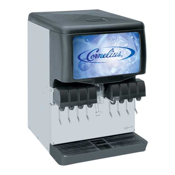
Cornelius ED175 Installation Manual
Kit base unit
Hide thumbs
Also See for ED175:
- Training manual (48 pages) ,
- Installation instructions manual (7 pages)
Summary of Contents for Cornelius ED175
- Page 1 KIT BASE UNIT ED175 Installation Manual Publication Number: 629097525INS Release Date: July 08, 2016 Revision: A Visit the Cornelius web site at www.cornelius.com for all your Literature needs.
- Page 2 Commercial Warranty. Cornelius will not be responsible for any repair, replacement or other service required by or loss or damage resulting from any of the following occurrences, including but not limited to, (1) other than normal and proper use and normal...
-
Page 3: Table Of Contents
TABLE OF CONTENTS Safety Instructions ..............1 Read and Follow ALL Safety Instructions . -
Page 5: Safety Instructions
KIT Base Unit ED175 Installation Instructions SAFETY INSTRUCTIONS ALL S EAD AND OLLOW AFETY NSTRUCTIONS Safety Overview • Read and follow ALL SAFETY INSTRUCTIONS in this manual and any warning/caution labels on the unit (decals, labels or laminated cards). • Read and understand ALL applicable OSHA (Occupational Safety and Health Administration) safety regulations before operating this unit. -
Page 6: Safety Precautions
KIT Base Unit ED175 Installation Instructions AFETY RECAUTIONS This unit has been specifically designed to provide protection against personal injury. To ensure continued protection observe the following: WARNING: Disconnect power to the unit before servicing following all lock out/tag out procedures established by the user. Verify all of the power is off to the unit before any work is performed. -
Page 7: Instructions
Disconnect Electrical power and turn off primary regulator on CO tank in Back-Room Package (or where applicable, if located in other area). NOTE: To convert BASE UNIT ED175 PLR to RENEW OR SHOTS, use this manual only. OOSE HIPPED ARTS •... -
Page 8: Installation
KIT Base Unit ED175 Installation Instructions INSTALLATION NOTE: Common Procedure For Renew & Shots. Remove the dummy merchandiser components by removing the push-in clips, as shown in Figure 1A and Figure 1B and recycle the merchandiser parts. Figure 1A. Figure 1B. - Page 9 KIT Base Unit ED175 Installation Instructions 4. Install sensor bracket with 1/8" rivets, included in this kit and connect interlock harness to reed switch, see Figure 4. Figure 4. 5. Connect interlock harness to door switch as shown in Figure 5A & Figure 5B. Install door switch bracket with 1/8"...
-
Page 10: Flavor Shot Timing
KIT Base Unit ED175 Installation Instructions LAVOR SHOT TIMING Locate the flavor shot controller on the front of the E-box cover.See Figure 7 for dip switch settings. Figure 7. LAVOR SHOT SETTINGS Flavor Shot Time 1 Second Flow Rate 0.3 Oz/sec (9 ml or 9 gm) -
Page 11: Electrical Hook-Ups (Shots Units Only)
KIT Base Unit ED175 Installation Instructions LECTRICAL HOTS NITS NOTE: Continue with steps 1 through 11 for shots units only. Remove baffles and metal covers from above and behind the valve area (See Figure 8). NOTE: This is not easy due to space constraints but can be accomplished using a short stubby #2 Phillips screwdriver or by rotating entire electrical box forward enabling use of standard #2 Phillips screwdriver. - Page 12 KIT Base Unit ED175 Installation Instructions Figure 10. 4. Connect the 30" jumpers to the control board & route the jumpers out of electrical box through the bushing installed in the above step (See Figure 6). NOTE: Agitation will occur.
- Page 13 KIT Base Unit ED175 Installation Instructions 6. Beverage tubing (1/4 I.D.) should be routed from back of valve panel to center area where soda valve hook- ups from cold plates are located. 7. Install lower and upper portion of Ice chute cover using the washers and nuts.
- Page 14 KIT Base Unit ED175 Installation Instructions 15. Snap the nozzle vertical support bracket over the cross member (See Figure 17D). NOTE: Step 15 is for Shots units only. Figure 17A. Figure 17B. Figure 17D. Figure 17C. 16. Insert 4 bushing into the LED backlight hinges (See Figure 18A).
- Page 15 KIT Base Unit ED175 Installation Instructions Figure 18A. Figure 18B. Figure 18C. Figure 18D. NOTE: Continue with steps 20 and 21 for Renew Unit only. 20. Install the new merchandiser onto the unit. 21. Install drip tray. Figure 19. © 2016, Cornelius Inc.
-
Page 16: Electrical Testing (Shots Units Only)
KIT Base Unit ED175 Installation Instructions LECTRICAL ESTING HOTS NITS Set-up syrup flavors in Back-Room Package area, as shown in BRP set-up. Figure 20. ED175 Plumbing/Electrical Connections 2. Connections to dispenser can proceed once the Back-Room Package items have been installed and tubing from BRP have been run to dispenser. -
Page 17: Start-Up (Shots Units Only)
KIT Base Unit ED175 Installation Instructions TART HOTS NITS 1. Reconnect power to dispenser and turn on primary regulator on CO tank in Back-Room Package. 2. Actuate keypad to purge syrup through beverage tubing and through inner nozzle. Initial purging can also be accomplished by removing the merchandiser with the harness still connected to control board. -
Page 18: Troubleshooting
KIT Base Unit ED175 Installation Instructions ROUBLESHOOTING FLAVOR SYRUPS DO NOT DISPENSE • No 24 volt power to PC board. • No CO pressure. • Empty syrup tank. • Kinked tubing. • Clogged inner nozzle. • Defective PC board. • Defective harness from keypad. - Page 20 Cornelius Inc. www.cornelius.com...


Need help?
Do you have a question about the ED175 and is the answer not in the manual?
Questions and answers