Table of Contents
Advertisement
Quick Links
Advertisement
Table of Contents

Subscribe to Our Youtube Channel
Related Manuals for Danfoss DGS Series


Summary of Contents for Danfoss DGS Series
- Page 1 User Guide Danfoss Gas Sensor Type DGS danfoss.com...
-
Page 2: Table Of Contents
User Guide | Danfoss Gas sensor, type DGS Contents Intended use ...........................3 Introduction ............................3 Installation and maintenance .......................3 3.1 Technician use only! ............................3 3.2 Regular Test ................................3 3.3 Location .................................. 3 3.4 Dimensions and appearance ..........................4 3.5 Cable gland opening ............................4 3.6 Board pinout ................................. -
Page 3: Intended Use
User Guide | Danfoss Gas sensor, type DGS Intended use This document has the intent to provide the guidelines to avoid possible damages deriving from overvoltage and other possible issues resulting from the connection to the DGS power supply and the serial communication network. -
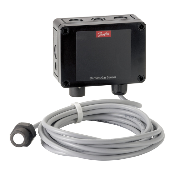
Page 4: Dimensions And Appearance
User Guide | Danfoss Gas sensor, type DGS 3.4 Dimensions and appearance Fig. 1 3.5 Cable gland opening Fig. 2 Danfoss 148H126_01-2018 Hole punching for cable gland: Continue precision punching with Remove potential burrs and secure small movements until the round flat surfaces. -
Page 5: Installation Instructions
User Guide | Danfoss Gas sensor, type DGS Status LED / B&L: * the duration and whether to include the relay GREEN is power on. status with this function or not is user defined. – flashing if maintenance needed DI_01 (terminals 1 and 2) is a dry-contact (potential-free) behaving identically to the YELLOW is an indicator of Error. -
Page 6: Installation Test
User Guide | Danfoss Gas sensor, type DGS Action Reaction Reaction Warning relay 1** Critical relay 3** Buzzer Light SPDT NO SPDT NC (Normally Open) (Normally closed) Loss of power to DGS X (closed) Gas signal < warning alarm GREEN threshold Gas signal >... -
Page 7: Troubleshooting
User Guide | Danfoss Gas sensor, type DGS 3.9 Troubleshooting Symptom: Possible cause(s): LED off • Check power supply. Check wiring. • DGS MODBUS was possibly damaged in transit. Check by installing another DGS to confirm the fault. Green flashing •... - Page 8 User Guide | Danfoss Gas sensor, type DGS DGS with Modbus network communication in combination with other devices powered by more than one power supply It is strongly recommended to use direct current power supply when: • more than 5 DGS units are powered by the same power supply •...
-
Page 9: Operation
38400 Baud. By removing the jumper, the baud rate is changed to 19200 Baud. Removing the jumper is required for integrating with Danfoss System Managers AK-SM 720 and AK-SM 350. Jumper 5, JP5, located at the top left, is used to configure the analogue output type. -
Page 10: Function Of The Keys And Leds On The Keypad
User Guide | Danfoss Gas sensor, type DGS 4.1 Function of the keys and Exits programming, returns to the previous menu level. LEDs on the keypad Enters sub menus, and saves parameter settings. Scrolls up & down within a menu, changes a value. -
Page 11: Menu Overview
User Guide | Danfoss Gas sensor, type DGS Menu overview Menu operation is done via a clear, intuitive and logical menu structure. The operating menu contains the following levels: • Starting menu with indication of the device type if no sensor head is registered, otherwise scrolling display of the gas concentrations of all registered sensors in 5-second intervals. -
Page 12: Error Status
User Guide | Danfoss Gas sensor, type DGS Menu overview Start menu (continued) Main menu Service The following menu items are only accessible with Service ON (password protected) !! Service ON = special mode = fault message is active!! Alarm reset settings See chapter 5.6... -
Page 13: Alarm Status
User Guide | Danfoss Gas sensor, type DGS 5.2 Alarm Status Display of the currently pending alarms in plain text in the order of their arrival. Only those sensor heads are displayed, where at least one alarm is active. Alarms in latching mode (latching mode is only valid for certain DGS types, DGS-PE) can be acknowledged in this menu (only possible if the alarm is not active). -
Page 14: Display Parameters
User Guide | Danfoss Gas sensor, type DGS 5.5 Display Parameters In the menu display parameters you can find the general parameters of the Service Tool and the DGS. Display Parameters 5.5.1 Software Version Software Version XXXXX - YYYYY Software version of the hand-held Service Tool and of the DGS. -
Page 15: Alarm Reset Duration
User Guide | Danfoss Gas sensor, type DGS 5.6.2 Alarm reset duration This defines how long the alarm reset is active (alarm acknowledged). Time Symbol Description Default Function Reset Alarm Relay Rst Enable Defines how many seconds the alarm reset condition... -
Page 16: Ao Settings
User Guide | Danfoss Gas sensor, type DGS 5.8 AO Settings Analog Output 1 AO Settings 50% -- min = 0 V. This menu is for the configuration of the analogue outputs. If more than one sensor head is present, the maximum value of the two measurements is assigned to the output. -
Page 17: Operating Data
User Guide | Danfoss Gas sensor, type DGS 5.9 Operating Data This menu is for retrieving relevant operational data from the sensor head. No changes or modifications are possible. Operating Data Operating Data If more than one sensor head is connected to the DGS, the selection is done at X. -
Page 18: Calibration
User Guide | Danfoss Gas sensor, type DGS 5.10 Calibration This section gives an overview of the calibration menu. The calibration description can be found on the following pages. For HFC, remember to use the specified calibration gas. (HFC grp 1 = R1234yf, grp 2 = R134a, grp 3 = R407c) -
Page 19: Zero Calibration
User Guide | Danfoss Gas sensor, type DGS 5.10.1 Zero calibration The stepwise calibration process is described below. Note: The specified warm-up times etc. must be strictly observed before starting the calibration process. Zero DP 1 Step 1: Display of the current value. -
Page 20: Gain Calibration
User Guide | Danfoss Gas sensor, type DGS 5.10.2 Gain calibration The stepwise calibration process is described below. Note: The specified warm-up times etc. must be strictly observed before starting the calibration process. Enter concentration of the test gas used. -
Page 21: Zero Point Calibration Of Analogue Output
User Guide | Danfoss Gas sensor, type DGS 5.10.3 Zero point calibration of With this menu item you can adjust the zero point of the analogue output (4mA). The zero point analogue output correction is only possible when the minimum output is 2 V or 4 mA, i.e. not possible when minimum output is 0 V or 0 mA. -
Page 22: Modbus Menu Survey
User Guide | Danfoss Gas sensor, type DGS MODBUS menu survey Function Min. Max. Factory Unit AKM name Gas level Sensor 1 Actual gas level in % of range 100.0 Gas level % Sensor 1 Actual gas level in ppm... - Page 23 User Guide | Danfoss Gas sensor, type DGS Readout the attached gas sensor type. Sensor type 1: HFC grp 1 R1234ze, R454C, R1234yf R1234yf, R454A, R455A, R452A R454B, R513A 2: HFC grp 2 R407F, R416A, R417A R407A, R422A, R427A R449A, R437A, R134A...
-
Page 24: Ordering
HFC grp 3: R448A, R125, R404A, R32, R507A, R434A, R410A, R452B, R407C, R143B Bold = calibration gas Note: DGS is also available for alternative refrigerant gases on request. Please contact your local Danfoss sales office for details. © Danfoss | Climate Solutions | 2022.01...
Need help?
Do you have a question about the DGS Series and is the answer not in the manual?
Questions and answers