Advertisement
Installation Guide
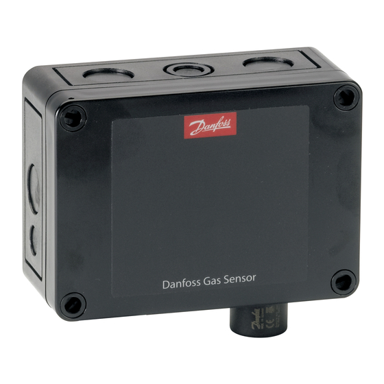
Danfoss Gas Sensor
DGS
Technician use only!
This unit must be installed by a suitably qualified technician who
will install this unit in accordance with these instructions and the
standards set down in their particular industry/country.
Suitably qualified operators of the unit should be aware of the
regulations and standards set down by their industry/country for
the operation of this unit.
These notes are only intended as a guide and the manufacturer
bears no responsibility for the installation or operation of this unit.
Failure to install and operate the unit in accordance with these
instructions and with industry guidelines may cause serious injury
including death and the manufacturer will not be held responsible
in this regard.
It is the installer's responsibility to adequately ensure that the
equipment is installed correctly and set up accordingly based on
the environment and the application in which the products are
being used.
Dimensions and appearance
1
© Danfoss | DCS (ADAP-KOOL®) | 2018.12
ENGLISH
Please observe that DGS works as a safety device securing a
reaction to a detected high gas concentration. If a leakage
occurs, the DGS will provide alarm functions, but it will not
solve or take care of the leakage root cause itself.
Regular Test
To maintain product performance and comply with the local
requirements the DGS must be tested regularly.
DGS's are provided with a test button that may be activated to
validate the alarm reactions.
Additionally the sensors must be tested by either bump test or
calibration.
Danfoss recommends the following minimum calibration intervals:
DGS-IR: 60 months
DGS-SC: 12 months
DGS-PE: 6 months
With DGS-IR it is recommended to do an annual bump test in years
without calibration.
Check local regulations on calibration or testing requirements.
After exposure to a substantial gas leak, the sensor should be
checked by bump test or calibration and replaced if necessary.
Location:
For all gas' heavier than air, Danfoss recommends locating the
sensor head app. 30cm (12") above the floor and if possible in the
air flow. All gas' measured with these DGS-sensors are heavier than
air: HFC grp 1, HFC grp 2, HFC grp 3, CO2 and Propane.
For further details on Test and Location please see the Danfoss Gas
Detection application guide, DKRCI.PA.S00.A-.02
RI8SP202 | 1
Advertisement
Table of Contents

Subscribe to Our Youtube Channel
Related Manuals for Danfoss DGS


Summary of Contents for Danfoss DGS
- Page 1 DGS-SC: 12 months in this regard. DGS-PE: 6 months With DGS-IR it is recommended to do an annual bump test in years It is the installer’s responsibility to adequately ensure that the without calibration. equipment is installed correctly and set up accordingly based on Check local regulations on calibration or testing requirements.
- Page 2 JP4 closed → 38400 Baud (default) * JP5 open → AO 0-20 mA JP5 closed → AO 0-10 Volt (default) Note: the DGS must be power cycled before any change to JP4 take effect. © Danfoss | DCS (ADAP-KOOL®) | 2018.12...
- Page 3 For convenient commissioning, the DGS is pre-configured and parameterized with factory-set defaults. See Menu Survey. The DGS is available with one sensor or two sensors and B&L Jumpers are used to change the analogue output type and the (Buzzer and Light) as option (see figure 1).
- Page 4 DGS Installation test As DGS is a digital device with self-monitoring, all internal errors are visible via the LED and Modbus alarm messages. All other error sources often have their origins in other parts of the installation. For fast and comfortable Installation test we recommend proceeding as follows.
- Page 5 High (critical and warning) alarm delay in seconds, if set to 0: no delay 0 2:Alarm delay s Service Status of the sensors warm up period DGS Warm-up 0:Ready 1: Warming Up 1 or more sensors © Danfoss | DCS (ADAP-KOOL®) | 2018.12 RI8SP202 | 5...
- Page 6 0: OK, sensor in place Sensor removed 1: Fault, Sensor out or removed, or wrong sensor placed in 0: OK, Sensor not due for calibration Calibrate sensor 1: Warning, Due for calibration © Danfoss | DCS (ADAP-KOOL®) | 2018.12 RI8SP202 | 6...
- Page 7 Indication if the normal alarm function is inhibited or in normal Alarm inhibited operation 0: Normal operation, i.e. alarms are created and cleared 1: Alarms inhibited, i.e. alarm status is not updated, e.g. due to DGS in test mode Critical Limit alarm 2:Criti. limit...
- Page 8 Danfoss can accept no responsibility for possible errors in catalogues, brochures and other printed material. Danfoss reserves the right to alter its products without notice. This also applies to products already on order provided that such alternations can be made without subsequential changes being necessary in specifications already agreed.
Need help?
Do you have a question about the DGS and is the answer not in the manual?
Questions and answers