Table of Contents
Advertisement
Quick Links
Installation Instructions
300 A Current Sensor Kit for
D1h/D3h/D5h/D6h Drives
®
VLT
FC Series FC 102, FC 103, FC 202, FC 302
1.1 Description
The 300 A current sensor kit contains all components required
to upgrade the current sensor assembly in D1h/D3h/D5h/D6h
drives. The kit is compatible with the power ratings shown in
Table 1.1. To identify the power rating, see
chapter 1.1.1 Identifying the Power Rating.
Product group and series
®
VLT
HVAC Drive FC 102,
®
VLT
Refrigeration Drive FC 103,
®
VLT
AQUA Drive FC 202
®
VLT
AutomationDrive FC 302
Table 1.1 Applicable Power Range for 300 A Current Sensor Kit
1.1.1 Identifying the Power Rating
To find the drive power rating, use the following steps:
1.
Obtain the following information from the
nameplate, which is on the drive. Refer to
Illustration 1.1.
•
Product group and drive series
(characters 1–6)
•
Power rating (characters 7–10)
•
Voltage rating (phases and mains)
(characters 11–12)
2.
Determine if the power rating is in Table 1.1.
Voltage rating
Power rating [kW
(V)
(hp)]
(T4) 380–480
110–200
(150–300)
(T7) 525–690
75–315
(75–350)
(T5) 380–500
90–160
(125–200)
(T7) 525–690
55–250
(75–350)
Danfoss A/S © 07/2018 All rights reserved.
1
Product group and drive series
2
Power rating
3
Voltage rating (phases and mains)
Illustration 1.1 Example Nameplate
1.1.2 Kit Ordering Number
Kit number
Kit description
176F6516
300 A Current Sensor Conversion Kit for
D1h/D3h/D5h/D6h
Table 1.2 Number for 300 A Current Sensor Kit
MI70Y202
Advertisement
Table of Contents

Subscribe to Our Youtube Channel
Related Manuals for Danfoss 176F6516


Summary of Contents for Danfoss 176F6516
-
Page 1: Installation Instructions
Illustration 1.1. • Product group and drive series (characters 1–6) • Power rating (characters 7–10) • Voltage rating (phases and mains) (characters 11–12) Determine if the power rating is in Table 1.1. Danfoss A/S © 07/2018 All rights reserved. MI70Y202... -
Page 2: Safety Information
• Before performing any service or repair work, use an appropriate voltage measuring device to make Only qualified, Danfoss-authorized personnel are allowed to sure that the capacitors are fully discharged. install the parts described in these installation instructions. Handling of the drive and its parts must be done in NOTICE accordance with the corresponding operating guide. -
Page 3: General Torque Tightening Values
RFI filter or mains fuses. Class B: Clamping PCA or plastic Illustration 1.2 shows the AC input busbars with no input options. Illustration 1.3 shows the AC input busbars with optional RFI filter and mains fuses. MI70Y202 Danfoss A/S © 07/2018 All rights reserved. - Page 4 Remove 3 nuts (13 mm) at the top of the AC input busbars, 1 per phase. Remove 3 nuts (13 mm) at the bottom of the AC input busbars, 1 per phase. Danfoss A/S © 07/2018 All rights reserved. MI70Y202...
- Page 5 Remove the motor terminal block by sliding it down to release it from the 2 metal retaining clips. Remove the 3 cylinder busbars, 1 from the center of each current sensor and discard the busbars. MI70Y202 Danfoss A/S © 07/2018 All rights reserved.
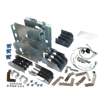
- Page 6 FC Series FC 102, FC 103, FC 202, FC 302 1 Current sensor 4 Mixing fan cable 2 Thread-cutting screw (T20) 5 Mixing fan 3 Power terminal mounting plate 6 Mixing fan slot Illustration 1.4 Power Terminal Mounting Plate Danfoss A/S © 07/2018 All rights reserved. MI70Y202...
-
Page 7: Assembly Guidelines
M8 nut M4x10 thread-forming screw Mixing fan Wire harness (current sensor cables) Mixing fan housing – Power terminal mounting plate, not shown (IP20/Chassis) Illustration 1.5 Exploded View of 300 A Current Sensor Kit MI70Y202 Danfoss A/S © 07/2018 All rights reserved. - Page 8 For IP21/Type 1 and IP54/Type 12 enclosures only, fasten 3 screws (T25) at the bottom of the drive. For IP20/Chassis enclosures only, fasten 3 M8 nuts. Danfoss A/S © 07/2018 All rights reserved. MI70Y202...
- Page 9 Select the appropriate procedure for the drive: Reconnect wiring to motor terminals, and replace the U/V/W terminal label. • No options • Mains fuses only • RFI filter only • Mains fuses and RFI filter MI70Y202 Danfoss A/S © 07/2018 All rights reserved.
- Page 10 (T25). Danfoss can accept no responsibility for possible errors in catalogues, brochures and other printed material. Danfoss reserves the right to alter its products without notice. This also applies to products already on order provided that such alterations can be made without subsequential changes being necessary in specifications already agreed. All trademarks in this material are property of the respective companies. Danfoss and the Danfoss logotype are trademarks of Danfoss A/S.
Need help?
Do you have a question about the 176F6516 and is the answer not in the manual?
Questions and answers