Table of Contents
Advertisement
Advertisement
Table of Contents
Troubleshooting

Related Manuals for Thermo Scientific Heraeus MULTIFUGE 3S+


Summary of Contents for Thermo Scientific Heraeus MULTIFUGE 3S+
- Page 1 Heraeus 3S+ / 3SR+ ® ULTIFUGE Instruction Manual...
- Page 2 How to use this manual Use this manual to get acquainted with your centrifuge and its accessories. Overleaf you will find a graphic representation of the control panel The manual helps you to avoid inappropriate han- with a survey of the most important dling.
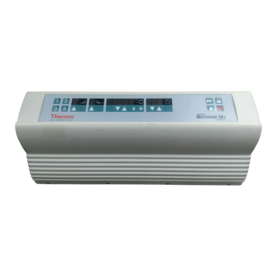
- Page 3 (only for instruments with refrigeration unit) acceleration deceleration temperature profiles profiles run time Quick run speed/RCF program selection open lid stop start rpm/RCF Bucket selection pre-temperature-regulation switch key "set" keys "set" keys display Before switching on the centrifuge please read this manual The mains switch is located on the right-hand side panel.
- Page 4 ® Keys Control panel of the Multifuge 3S+ / 3SR+ start : normal start of the centrifuge Display panels stop : manual stop of a run open lid: open lid (possible only with the instrument Program selection switched on) Key 1 - 4 : store or recall programs.
-
Page 5: Table Of Contents
Contents Contents For your safety..........3 Operation ..........47 Safety instructions in this manual ......3 Switching on the centrifuge ........47 Proper use..............4 Actuating the lid............47 Improper use ............4 Opening the lid ........... 47 Centrifuging hazardous materials ......4 Closing the lid ............. - Page 6 Contents Imbalance display........... 58 Troubleshooting ........71 Changing the settings during the run ..... 58 Emergency lid release..........71 Stopping the centrifuge .......... 59 Error troubleshooting..........73 Stopping with preset run time ......59 Contacting Thermo Service........82 Stopping with continuous operation ....59 Technical Data ..........
-
Page 7: For Your Safety
For your safety For your safety Thermo centrifuges are manufactured according to current technical standards and regulations. Nonethe- less, centrifuges may pose danger to individuals and Safety instructions in this manual surrounding if • they are not used as designed This symbol denotes potential hazards •... -
Page 8: Proper Use
For your safety If microbiological samples of risk group II (according Proper use to "Laboratory Bio-safety Manual" of WHO) are be- The centrifuge is designed to separate liquid- ing centrifuged, aerosol-tight bio-seals have to be suspended materials having different densities and used. -
Page 9: Conformity To Current Standards
For your safety • Strictly follow the rules and regulations for cleaning Conformity to current standards and disinfection. Thermo centrifuges are manufactured and tested • If the rotor or the rotor lid shows signs of corrosion according to the following standards and regulations or wear, you must stop using it. - Page 10 For your safety for your notes...
-
Page 11: The Multifuge 3S+ / 3Sr
® Description of the Multifuge Description ® The Multifuge 3S+ / 3SR+ ® The Multifuge 3S+ / 3SR+ is a general-purpose table- ® The figure below shows a Multifuge 3SR+ with the lid top centrifuge for biotechnological and pharmaceutic open and a swinging bucket rotor installed. research that moves high capacity centrifugation onto the fast track. -
Page 12: Safety Systems
® Description of the Multifuge Safety systems Parts supplied ® The Multifuge is equipped with a number of safety Accessories supplied with the centrifuge are: systems: − power cord • Housing and lid is constructed of 8 mm steel. • Lid with window −... -
Page 13: Function And Features
® Description of the Multifuge Function and features Basic unit/ function Description / feature Cabinet / frame galvanized steel plate box with casing bowl Chamber stainless steel Drive Brushless induction drive Key pad and display key pad and display elements covered by an easy-care continuous surface Control Microprocessor driven by "Easycontrol II"... - Page 14 ® Description of the Multifuge The Easycontrol user interface Function Feature Program memory keys freely programmable Acceleration / deceleration profile 1 = slowest, ... 9 = fastest acceleration / deceleration curve Setting speed by rpm adjustable from 300 rpm to 15 000 rpm, in 10 rpm increments RCF selection upon activation of RCF switch , the RCF value can then be entered Time selection...
- Page 15 ® Description of the Multifuge Function Feature Lid opening automatic unlocking via ”Open lid“ key ( (unlocking in case of power failure: see chapter ”Troubleshooting“) Start start key ( Stop stop key ( "Quick Run“ mode pressing the "Quick Run“ key ( ) activates maximum acceleration up to the maximum permissible speed of rotor;...
- Page 16 ® Description of the Multifuge Notes...
-
Page 17: Before Use
Before use Before use The centrifuge can be damaged by Centrifuge transport and installation jolting during the transport! After opening the box remove the protective materials. Transport the centrifuge only in the upright position using proper con- tainment and secure it properly. When transporting centrifuge,... -
Page 18: Main Connection
Before use Main connection • The centrifuge must be protected from heat and direct sunlight. Connect the centrifuge only to an grounded main • The location must be well ventilated at all times. power supply. Make sure that the power cord is com- patible with the safety regulations valid, and that your main voltage and frequency correspond to the specifi- UV rays reduce the durability of... -
Page 19: Rotors And Accessories
Rotors and accessories Rotors and accessories ® A rotor is not included as part of a Multifuge 3S+ or 3SR+ centrifuge. A large variety of rotors are available as accessories. In addition, there are adapters and reduction sleeves for a variety of commercially available tubes and bottles. -
Page 20: Rotors For The Multifuge
Rotors and accessories ® Rotors for the Multifuge ® Table 1: Rotors for differences of 120V instruments are shown in parentheses Multifuge Rotor designation Swinging Bucket Rotor 7500 6445 (7500 6434 with integrated locking mechanism) With bucket Round bucket Rectangular bucket Carrier for 750 ml 250 ml... - Page 21 Rotors and accessories ® Table 1: Rotors for differences of 120V instruments are shown in parentheses Multifuge Rotor designation Swinging Bucket Rotor 7500 6445 (7500 6434 with integrated locking mechanism) With bucket Tissue culture bucket Multiple carriers Multiple carriers 250 ml 25 x 5 / 7 ml 20 x 10 / 15 ml 7500 6497...
- Page 22 Rotors and accessories ® Table 1: Rotors for differences of 120V instruments are shown in parentheses Multifuge Rotor designation Swinging Bucket Rotor 7500 6445 (7500 6434 with integrated locking mechanism) Multiple carriers Multiple carriers With bucket 17 x 15 ml 7 x 50 ml Order no.
- Page 23 Rotors and accessories ® Table 1: Rotors for Multifuge differences of 120V instruments are shown in parentheses ® ® BIOshield Rotor Highplate Rotor Rotor designation 4 x 250 ml 2 x 5 plates Order no. 7500 6435 7500 6444 Maximum permissible load [ g ] 4 x 600 2 x 500 Maximum speed n...
- Page 24 Rotors and accessories Table 1: Rotors for Multifuge® 3S+ differences of 120V instruments are shown in parentheses Fixed-Angle Rotor Highconic® Rotor Rotor designation 6 x 94 ml 6 x 50 ml 7500 3334 7500 3057 Order no. Maximum permissible load [ g ] 6 x 140 6 x 130 Maximum speed nmax [ rpm ]...
- Page 25 Rotors and accessories ® ® FIBERLite Carbon Fiber Rotors for Multifuge For a safe and proper use, please refer to the instruction manual of the centrifuge and the FIBERLite® rotor manual. ® Table 1: Fixed Angle Rotors for Multifuge differences of 120V instruments are shown in parentheses F13-14x50cy F14-6x250 LE F15-8x50c...
-
Page 26: Rotors For The Multifuge
Rotors and accessories ® Rotors for the Multifuge 3SR+ ® Table 2: Rotors for differences of 120V instruments are shown in parentheses Multifuge 3SR+ Rotor designation Swinging Bucket Rotor 7500 6445 (7500 6434 with integrated locking mechanism) With bucket Round buckets Rectangular buckets Carrier for 750 ml... - Page 27 Rotors and accessories ® Table 2: Rotors for Multifuge 3SR+ differences of 120V instruments are shown in parentheses Rotor designation Swinging Buckets Rotor 7500 6445 (7500 6434 with integrated locking mechanism) With bucket Tissue culture bucket Multiple carriers Multiple carriers 250 ml 25 x 5 / 7 ml 20 x 10 / 15 ml...
- Page 28 Rotors and accessories ® Table 2: Rotors for differences of 120V instruments are shown in parentheses Multifuge 3SR+ Rotor designation Swinging Buckets Rotor 7500 6445 (7500 6434 with integrated locking mechanism) With bucket Multiple carriers Multiple carriers 17 x 15 ml 7 x 50 ml Order no.
- Page 29 Rotors and accessories ® Table 2: Rotors for Multifuge 3SR+ differences of 120V instruments are shown in parentheses ® ® Rotor designation BIOshield Rotor Highplate Rotor 4 x 250 ml 2 x 5 plates Order no. 7500 6435 7500 6444 Maximum permissible load [ g ] 4 x 600 2 x 500...
- Page 30 Rotors and accessories ® Table 2: Rotors for Multifuge 3SR+ differences of 120V instruments are shown in parentheses ® Micro Liter Rotor Fixed-Angle Rotor Highconic Rotor Rotor designation 24 x 2.0 ml 6 x 94 ml 6 x 50 ml 7500 3332 7500 3334 7500 3057...
- Page 31 Rotors and accessories ® Table 2: Rotors for Multifuge 3SR+ differences of 120V instruments are shown in parentheses Micro Liter Rotor Fixed-Angle Rotor BIO Shield 600 Rotor designation 48 x 2,0 ml FA12-94 4 x 150 ml 7500 3348 6 x 94 ml / 12 x 16 ml 7500 2005 Order no.
- Page 32 Rotors and accessories ® ® FIBERLite Carbon Fiber Rotors for Multifuge 3SR+ For a safe and proper use, please refer to the instruction manual of the centrifuge and the FIBERLite® rotor manual. ® Table 2: Fixed Angle Rotors for Multifuge 3SR+ differences of 120V instruments are shown in parentheses) Rotor type...
- Page 33 Rotors and accessories Adapter Table 3: Adapter (1) * max. tube length with aerosol-tight cap max. tube Adapter and accessories for dimensions tubes color order no. d x length / * diameter round buckets 7500 6441 [ mm ] [ mm ] rotor ®...
- Page 34 Rotors and accessories Table 3: Adapter (2) * max. tube length with aerosol-tight cap max. tube Adapter and accessories for dimensions tubes color order no. d x length / * diameter round buckets 7500 6441 [ mm ] [ mm ] rotor Adapter 37 x 5 ml, Decant, Set/4 12.0 x 110 mm...
- Page 35 Rotors and accessories Table 3: Adapter (3) * max. tube length with aerosol-tight cap max. tube Adapter and accessories for dimensions tubes color order no. d x length / * diameter round buckets 7500 6441 [ mm ] [ mm ] rotor Adapter 7 x 15 ml Vacutainer, Set/4 16.5 x 120 mm...
- Page 36 Rotors and accessories Table 3: Adapter (4) * max. tube length with aerosol-tight cap max. tube Adapter and accessories for dimensions tubes color order no. d x length / * diameter round buckets 7500 6441 [ mm ] [ mm ] rotor T 25 Cell culture bottle adapter see Manipulation indication...
- Page 37 Rotors and accessories Table 3: Adapter (5) * max. tube length with aerosol-tight cap max. tube dimensions tubes color order no. Adapter and accessories for d x length / * diameter rectangular buckets 7500 6446 [ mm ] [ mm ] rotor ®...
- Page 38 Rotors and accessories Table 3: Adapter (6) * max. tube length with aerosol-tight cap max. tube Adapter and accessories for dimensions tubes color order no. ® d x length / * diameter BIOshield Rotor 7500 6435 [ mm ] [ mm ] rotor ®...
- Page 39 Rotors and accessories Table 3: Adapter (7) Adapter for max. tube dimensions tube capacity number color order no. Micro Liter Rotor 7500 3332 x length [ mm ] [ ml ] per set Reduction sleeve PCR 6.2 x 20 grey 7600 3750 Reduction sleeve 8 x 43.5...
- Page 40 Rotors and accessories Table 3: Adapter (8) max. tube number per number color order no. Adapter for Fixed-Angle Rotor dimensions adapter 7500 3334 x length rotor [ mm ] 1.5 ml micro tubes 11 x 51 nature 7600 2905 3.5 ml 11 x 95 nature 7500 3091...
-
Page 41: Handling The Rotor
Rotors and accessories Handling the rotor On swinging bucket rotors, at regular inter- vals, apply a light coating of lubricant to the rotor body trunnion pins and to the corre- sponding mating surfaces on the buckets! Lubricant 7000 6692 is supplied with the centrifuge. Swinging Bucket Rotor 7500 6445 (7500 6434 with locking mechanism) The various swinging buckets are split up into weight... - Page 42 Rotors and accessories Tissue culture bucket 7500 6497 Deepwell plates can also be inserted in the carrier without using plate holder. Large volume tissue culture tubes of 175 to 250 ml capacity, available from various manufacturers, can be Insert the individual plate holders as shown in the illus- used directly.
- Page 43 Rotors and accessories ® BIOshield Rotor 7500 6435 The bucket set is a permanent part of the rotor and must not be interchanged with any different rotor. Do not run the rotor without the rotor cover installed. The rotor cover is installed and removed by pushing down and turning the cover locking knob.
- Page 44 Rotors and accessories ® The following examples are intended to illustrate the Highplate Rotor 7500 6444 different estimates of rotor life for various typical every- Do not run the rotor without the rotor cover installed. day use: Profile of use Max.
- Page 45 Rotors and accessories ® Handling micro plates Highconic - Rotor 7500 3057 Remove the appropriate plate holder from the carrier body for loading and unloading ® micro plates in the Highplate Rotor 7500 6444. Before loading, ensure that the rubber bottom is placed in the cut-outs of the bottom of the plate holder.
-
Page 46: Aerosol-Tight Operation
Rotors and accessories Aerosol-tight operation Use the special lubricant 7600 3500 only to grease the seals ! Aerosol-tight rotors and tubes are only to be opened in an approved safety Spare parts are delivered with the rotor or may be or- work bench when centrifuging danger- dered separately. - Page 47 Rotors and accessories ® BIOshield -Rotor Closing the aerosol-tight bio-containment ® Highplate -Rotor After greasing the seal, turn the cover until it sits lightly on the bucket. The aerosol-tight bio-containment of air To achieve uniform seal, turn the cover clockwise by vessel rotors is only warrented in a 1½...
-
Page 48: Closing Highconic - Rotor Aerosol-Tightly
Rotors and accessories ® Closing Highconic - Rotor aerosol-tightly The hexagon wrench of the pliers should be used as a support tool to fasten and loosen the lid of the fixed angle rotor in order to achieve secure closing (insert the hexagon through the hole in the screw cap). -
Page 49: Checking Of Aerosol-Tight Bio-Containment
Rotors and accessories • Shaking the bucket releases the carbon dioxide of Checking of aerosol-tight bio-containment the water, and an excessive pressure is built up. The checking of the rotor type and bucket was done • Leaks are recognized by humidity release and according to the dynamic microbiological test proce- audible disinflation of gas mix. - Page 50 Rotors and accessories Notes...
-
Page 51: Operation
Operation Operation Switching on the centrifuge Locate the main power switch on the right-hand side of the front panel, and set it to the ON (I) position. For a couple of seconds the following reading appears in the Actuating the lid control panel: Opening the lid Press the "open lid"... -
Page 52: Installing The Rotor
Operation 4. The rotor must glide freely down the collet chuck Installing the rotor until it hits the lower stop. 5. If you have positioned the rotor correctly, you can Improper or improperly combined tighten the collet chuck easily using the hexagon accessories may cause severe dam- wrench supplied. -
Page 53: Loading The Rotor
Operation If you wish to centrifuge samples that together with the Loading the rotor adapters exceed the maximum permissible load, you Maximum loading must either reduce the sample volume or calculate the permissible speed n according to the following for- perm Overloading can result in destruction mula:... -
Page 54: Filling The Centrifuge Tubes
Operation Maximum permissible load difference Filling the centrifuge tubes The smaller the imbalance of the centrifuge, the better the separation effect, because as Check carefully whether your tubes imbalance is minimized, so is the resultant are approved for the respective RCF vibration that could affect separation quality. -
Page 55: Inserting The Centrifuge Tubes
Operation Inserting the centrifuge tubes Fixed-angle rotors: The rotor must be loaded symmetri- cally. Failure to do so can cause rotor imbalance, which may lead to noisy operation, affect separation quality, or result in imbalance detection shut- down, as well as introduce significant detrimental wear to the motor and drive system. - Page 56 Operation Swinging bucket rotors: Improper loading These examples are to be applied to the other rotors in an analogous manner! Proper loading...
-
Page 57: Entering Parameters
Operation Bucket selection for swinging bucket Entering parameters rotors Deceleration curves When running a swinging bucket rotor, the automatic ® The Multifuge offers 9 acceleration and deceleration rotor identification feature will recognize the rotor body profiles for optimal centrifuging of samples and gradi- and not determine which bucket or carrier is installed. -
Page 58: Selecting Speed
Operation number of seconds, then changes to permanent Selecting speed display. The speed is now stored. The centrifuge speed can be set to a minimum of 300 rpm and to a maximum of 15 000 rpm (depending on For faster operation, you may shift the flash- the rotor). -
Page 59: More About The Rcf Value
Operation More about the RCF value Selecting run time The relative centrifugal force (RCF) is given in multi- There are two time modes: standard and extended. ples of the earth gravity g. It is a dimensionless number In the standard time mode you can select a run time that allows one to compare the efficiency of separation between 1 min and 9 h 59 min or continuous operation or sedimentation of diverse instruments, since it is... -
Page 60: Continuous Operation
Operation If you keep the selected key pressed, the dis- Extended time mode play changes at first slowly and after a few You can optionally switch to the extended time mode. seconds at an accelerated pace. To switch it on or off press the program selection key Release the key as soon as you have reached and start the centrifuge simultaneously. -
Page 61: Selecting The Temperature
Operation The temperature display flashes for a number of sec- Selecting the temperature onds, then changes to the current value display. The You can select the temperature in the range of -9 °C to temperature set point is now stored. +40 °C. -
Page 62: Starting The Centrifuge
Operation Starting the centrifuge Imbalance display Once the rotor is properly installed, the main switch If rotor imbalance is detected, shortly after the rotor turned on and the lid is closed, you can start the centri- reaches 300 rpm, the message "bAL "... -
Page 63: Stopping The Centrifuge
Operation Stopping the centrifuge Temperature control during standby Stopping with preset run time Temperature control becomes active once the rotor has been identified. This is the case after a centrifuga- Normally the run time has been selected, and all you tion run exceeding 300 rpm. -
Page 64: Working With Programs
Operation Centrifuging with a program Working with programs After closing the centrifuge lid, call the desired program The 4 program selection keys offer the option of storing memory number using the program selection key and and recalling the individual centrifugation processes. press the start key If the rotor is started with a program the speed or RCF set point value of which exceeds the permissible one... -
Page 65: Quick Run
Operation ”Quick Run” Removing the rotor ® For short-term operation the Multifuge is equipped 1. Open the centrifuge lid. with a "Quick Run" function 2. Remove the rotor cover (on applicable rotors). Short-term centrifugation is started by pressing the 3. Unscrew the clamping sleeve counterclockwise "quick run"... -
Page 66: Audible Alarm
Operation Audible alarm Turning the centrifuge off Accompanying all error messages, a warning signal is By switching the main switch into "0“ position the cen- given out which only is silenced upon pressing any key. trifuge is turned off. You have the option of signaling the end of a run The main power switch should be turned off acoustically. -
Page 67: Weee Compliance
Operation WEEE Compliance: This product is required to comply with the European Union`s Waste Electrical & Electronic Equipment (WEEE) Directive 2002/96/EC. It is marked with the following symbol: Thermo has contracted with recycling/disposal compa- nies in each EU Member State, and this product should be disposed of or recycled through them. - Page 68 Operation Notes...
-
Page 69: Maintenance And Care
Maintenance and care Cleaning Maintenance and care Maintenance to be performed by the Pull mains plug before cleaning the customer instrument! For the protection of persons, environment and mate- rial you are obliged to clean the centrifuge regularly Clean the casing, the rotor chamber, the rotor and the and to disinfect it if necessary. -
Page 70: Disinfection
Maintenance and care Disinfection If a centrifuge tube containing infectious material leaks During cleaning liquids and espe- during a run, you have to disinfect the centrifuge im- cially organic solvents should not mediately. come into contact with the drive shaft and the ball bearing. Organic solvents may decompose Infectious material could enter the centri- the lubricant of the motor bearing. - Page 71 Maintenance and care Rotor and rotor chamber must be treated with a neu- 6. Turn the rotor head down and drain off the disinfec- tral, universal disinfectant. Best suited for this purpose tant. Thereafter thoroughly rinse rotor and lid with are disinfectant sprays, ensuring that all rotor and ac- water.
-
Page 72: Decontamination
Maintenance and care Decontamination For general radioactive decontamination, use a solu- Chemical additives to the steam are not tion of equal parts of 70% ethanol, 10% SDS and wa- permitted. ter. Follow this with ethanol rinses, then de-ionized water rinses, and dry with a soft absorbent cloth. Dis- pose of all washing solutions in appropriate radioactive Never exceed the maximum permis- waste containers! -
Page 73: The Thermo Service Offer
Maintenance and care The Thermo service offer Warranty conditions Thermo Laboratory Products recommends annual ser- The warranty period starts with the day of delivery. vicing of the centrifuge and the accessories by author- Within the warranty period the centrifuge is repaired or ized customer service or trained professionals. - Page 74 Maintenance and care Notes...
-
Page 75: Troubleshooting
Troubleshooting Troubleshooting Proceed as follows: 1. Make sure that the rotor is at a stand still Emergency lid release (observe through window in the cover). In case of a power failure the lid could not be opened normally using the electrical lid unlocking mechanism During a power failure it is impossible To permit unloading in this case, the centrifuge is to lock the lid once the emergency lid... - Page 76 Troubleshooting 4. After finished, push the cord back into the instru- ment and reinserting the plastic plug. Once the power is restored, you can connect the in- strument to the main supply and turn it on. Following the self test of the centrifuge, the lid may be closed and locked with the motor.
-
Page 77: Error Troubleshooting
Troubleshooting Error troubleshooting If problems other than those described in the following tables arise, you must contact your nearest authorized service. Error Symptom Possible causes and corrective measures Displays remain dark The drive stops. Mains power failure or not connected The rotor stops without 1. - Page 78 Troubleshooting Error Symptom Possible causes and corrective measures – Centrifuge is exceptionally Imbalance. noisy. 1. Stop the centrifuge by pressing the "stop" key, in case of emergency, unplug mains power cord. 2. Wait until the centrifuge comes to a complete stop. 3.
- Page 79 Troubleshooting Error Symptom Possible causes and corrective measures Message "rotor" appears Rotor decelerates with Set speed exceeds permissible maximum speed for the in display. delayed deceleration. rotor. (The same holds for RCF setting) A) For about 15 sec. the display shows alternately "rotor" and the maximum permissible speed or RCF for the installed, after the rotor identification.
- Page 80 Troubleshooting Error Symptom Possible causes and corrective measures E-01 Rotor stops without Internal program error. deceleration to standstill. Switch the instrument off and on again. Instrument cannot be If the error persists, contact service representative. E-13 operated. E-14 Rotor stops with Overtemperature in the centrifuge tank.
- Page 81 Troubleshooting Error Symptom Possible causes and corrective measures E-19 Instrument stops with No rotor present or rotor identification impossible. deceleration to standstill A) Check whether a certified rotor is inserted. after short starting-up. B) Please take care of the readability of the inscription of the swinging bucket rotor cross installed.
- Page 82 Troubleshooting Error Symptom Possible causes and corrective measures E-21 Instrument does not start or No rotor present or rotor identification impossible brakes to standstill. A) Check whether a certified rotor is inserted. B) Following a brief power failure, the rotor could not be identified.
- Page 83 Troubleshooting Error Symptom Possible causes and corrective measures E-29 Motor does not start. Motor or rotor blocked. 1. Switch instrument off and on again using the main switch. 2. Open the lid. 3. Check whether the rotor can turn freely. If you cannot clear the malfunction, contact a service representative.
- Page 84 Troubleshooting Error Symptom Possible causes and corrective measures E-32 Rotor stops without brake Overtemperature in the electronics. to standstill or does not Turn instrument off and unplug mains power cord. start. Check and clean ventilation slots if necessary. After about 60 min you can restart the instrument. Observe the max.
- Page 85 Troubleshooting Error Symptom Possible causes and corrective measures E-36 Rotor stops without brake Overcurrent or error in current measurement. to standstill. Switch the instrument off and on again. Instrument cannot be If the error persists, contact service representative. E-38 operated. E-39 Rotor stops without brake Speed control measurement exceeds permissible rotor...
-
Page 86: Contacting Thermo Service
Troubleshooting Subsequently, the following readings will be displayed Contacting Thermo Service for 5 seconds each: Should you require our Service, please advise us of the (numbers are examples) catalog and serial number of your instrument. You will Software version keyboard __526 find the pertinent information at the specifications, near the socket for the main plug. -
Page 87: Technical Data
Technical Data Technical Data Features specification - indoor use Ambient conditions - maximum elevation 2000 m (6562 ft) above sea level - max. relative humidity 80 % up to 31°C (88°F), linearly decreasing down to 50 % relative humidity at 40°C (104°F). Ambient temperature allowed +2 °C to +35 °C (36°F to 95°F) - Page 88 Technical Data Features specification ® Dimension (H x W x D) Multifuge 362 mm x 551 mm x 666 mm ( 14.3 x 21.7 x 26.2 inches ) ® Multifuge 3SR+ 362 mm x 733 mm x 666 mm ( 14.3 x 28.7 x 26.2 inches ) ®...
-
Page 89: Electrical Connections / Fuses
Technical Data Electrical connections / fuses Order no. Voltage Frequency Nominal Power Fuse protection of Fuse current consumption instrument protection of building safety fuse * thermic excess current release ® Multifuge 230 V 50/60 Hz 8,6 A 1250 W 10 A 16 AT 7500 4361 ®... - Page 90 Technical Data Notes...
-
Page 91: Appendix
Appendix Appendix Acceleration and deceleration profiles On the following pages you find acceleration and deceleration profiles for each rotor type respectively. - Page 92 Appendix Acceleration profiles Swinging bucket rotor 7500 6445 time [s]...
- Page 93 Appendix Deceleration profiles Swinging bucket rotor 7500 6445 time [s]...
- Page 94 Appendix Acceleration profiles ® BIOshield Rotor 7500 6435 ® Highplate Rotor 7500 6444 time [s]...
- Page 95 Appendix Deceleration profiles ® BIOshield Rotor 7500 6435 ® Highplate Rotor 7500 6444 time [s]...
- Page 96 Appendix Acceleration profiles Micro liter Rotor 7500 3332 time [s]...
- Page 97 Appendix Deceleration profiles Micro liter Rotor 7500 3332 time [s]...
- Page 98 Appendix Acceleration profiles ® Highconic Rotor 7500 3057 time [s]...
- Page 99 Appendix Deceleration profiles ® Highconic Rotor 7500 3057 time [s]...
- Page 100 Appendix...
-
Page 101: Speed/Rcf Diagrams
Appendix Speed/RCF diagrams = max. speed Speed/RCF diagram Swinging Bucket Rotor 7500 6445 (7500 6434) 10000 Tissue culture bucket = 4600 rpm = 5039 Round bucket 1000 Rectangular bucket Multiple carrier = 4600 rpm = 4500 Micro plate swing = 4600 rpm = 3761 1000 10000... - Page 102 Appendix Speed/RCF diagram ® BIOshield Rotor 7500 6435 10000 = 5850 rpm RCF (r ) = 6956 1000 1000 10000 speed (rpm)
- Page 103 Appendix Speed/RCF diagram ® Highplate Rotor 7500 6444 10000 = 5650 rpm RCF (r ) = 5806 1000 1000 10000 speed (rpm)
- Page 104 Appendix Speed/RCF diagram Micro liter Rotor 7500 3332 100000 = 15 000 rpm RCF (r ) = 21 885 = 8.7 cm = 5.9 cm 10000 1000 1000 10000 100000 speed (rpm)
- Page 105 Appendix Speed/RCF diagram Angle Rotor 7500 3334 100000 = 12 000 rpm = 10.1 cm RCF (r ) = 16 260 = 6.3 cm 10000 1000 1000 10000 100000 speed (rpm)
- Page 106 Appendix Speed/RCF diagram ® Highconic Rotor 7500 3057 100000 = 12.4 cm = 8500 rpm = 6.0 cm RCF (r ) = 10 016 10000 1000 1000 10000 speed (rpm)
-
Page 107: Index
Index Index acceleration and deceleration curves · 87 centrifuge exceptionally noisy · 74 acceleration profiles · 7 Centrifuge transport and installation · 13 Acceleration/decelaration profile · 10 Centrifuging with a program · 60 actual values · 54 changing settings adapter · 29 during run ·... - Page 108 Index symbol for potential · 3 error codes dangerous chemicals · 4 E-01 ... E-40 · 76 Deceleration curves · 53 deceleration profiles · 7 decontamination · 66 Description · 7 Description / feature · 9 filling the centrifuge tubes · 50 Diagnostic messages ·...
- Page 109 Index for denoting dangers and potential damage · 3 manual stopping · 59 imbalance · 50, 51 max. tube dimensions · 23, 24, 29, 30, 31, 32 imbalance · 58 Maximum loading · 49 imbalance detection · 8 maximum permissible filling volume · 44 indoor use ·...
- Page 110 Index problems RCF-value · 22, 23, 24, 25, 26, 27 handling · 73 RCF-value · 17, 18, 19, 20 program display readings symbols · 60 of control panel during run · 7 Program memory keys · 10 recycling · 63 program storing ·...
- Page 111 Index selecting with preset run time · 59 run time · 55 substructure · 13 Selecting speed · 54 Switching from speed to RCF display and vice versa · 53 selecting the temperature · 57 selecting the temperature · 57 service ·...
- Page 112 Index wear · 5...
- Page 114 International Contacts China India Japan Phone +86 21 68 65 45 88 Phone +91 22 55 42 94 94 Phone +81 454 53 92 20 +86 10 58 50 35 88 Other Asia Pacific Countries Phone +852 28 85 46 13 Austria Belgium Finland...
Need help?
Do you have a question about the Heraeus MULTIFUGE 3S+ and is the answer not in the manual?
Questions and answers