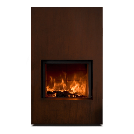
Stuv 21 Specifications & Manufacturer Installation Manual
Hide thumbs
Also See for 21:
- Installation and user instructions manual (94 pages) ,
- Installation manual (68 pages) ,
- Installation instructions manual (40 pages)
Advertisement
Quick Links
Advertisement

Summary of Contents for Stuv 21
- Page 1 STU ^ V 21: SPECIFICATIONS & MANUFACTURER INSTALLATION GUIDE...
- Page 2 Silicate board (40mm), stone (100mm minimum) or AAC block (75mm minimum). When installed on a combustible floor surface the Stûv 21 firebox must be positioned on top of an 18mm cement sheet floor plate and raised to a minimum height of 150mm using the appliance adjustable feet.
-
Page 3: Specifications
2. SPECIFICATIONS SINGLE FRONTED MODEL - STUV 21 DIMENSIONS (mm) STUV 21 / 95 SF STUV 21 / 105 SF STUV 21 / 125 SF STUV 21 / 135 SF 1050 1250 1350 1455 1040 1295 1040 1070 1170 OTHER DETAILS... - Page 4 2. SPECIFICATIONS DOUBLE FRONTED MODEL - STUV 21 Extended exhaust plate DIMENSIONS (mm) STÛV 21 / 95 DF STÛV 21 / 125 DF 1250 1455 1295 1070 OTHER DETAILS STÛV 21 / 95 DF STÛV 21 / 125 DF OUTPUT KW...
- Page 5 3. CLEARANCES - IMPORTANT When installed on a combustible floor surface the Stûv 21 firebox must be positioned on top of an 18mm cement sheet floor plate and raised to a minimum height of 150mm using the appliance adjustable feet.
- Page 6 4. INSTALLATION - FLOOR PREPARATION NON-COMBUSTIBLE SURFACE The Stûv 21 can be installed straight onto the surface with no prior preparation required. NON-COMBUSTIBLE FLOOR COMBUSTIBLE SURFACE The Stûv 21 must be installed on a 18mm tick cement sheet plate (minimum) and raised using the appliance’s adjustable feet so that the...
- Page 7 NON-COMBUSTIBLE FLOOR CAVITY LID 30MM SILICATE BOARD 70mm SILICATE BOARD COMBUSTIBLE WALL NON COMBUSTIBLE BOARD 100mm AIR GAP 50mm AIR GAP NON-COMBUSTIBLE FLOOR V 21 | MODEL SPECIFICATIONS PAGE 7...
- Page 8 When installed on a combustible floor surface the Stûv 21 firebox must be positioned on top of a 18mm cement sheet floor plate and raised to a minimum height of 150mm using the appliance adjustable feet. STÛV 21 / 125 SF/DF STÛV 21 / 95 SF/DF...
- Page 9 NON-COMBUSTIBLE FLOOR CAVITY LID 30MM SILICATE BOARD NON COMBUSTIBLE BOARD BRICKWORK 50mm AIR GAP NON-COMBUSTIBLE FLOOR V 21 | MODEL SPECIFICATIONS PAGE 9...
- Page 10 For installations where a combustible floor is situated in front of the Stûv 21 a non combustibe hearth (floor protector) is required. For installations where t he is raised and an Stûv 21 outside air kit is being fitted below the appliance...
- Page 11 900mm before a bend or elbow can be included in the flue run. Elbows or bends in the flue must be a maximum angle of 45º FLUE SYSTEM (Triple flue system) STÛV 21 /105 SF STÛV 21 / 135 SF STÛV 21 / 95 DF STÛV 21 / 125 DF 200mm...
- Page 12 V 21 | MODEL SPECIFICATIONS PAGE 12...
- Page 13 V 21 | MODEL SPECIFICATIONS PAGE 13...
- Page 14 4. INSTALLATION - SHELVES COMBUSTIBLE SHELF V 21 | MODEL SPECIFICATIONS PAGE 14...
- Page 15 The vertival distance between the hot air convection grill and the appliance is not limited. See fig I and J. Figure I 35cm (minimum) 155cm (minimum - from the base of the appliance) CONVECTION AIR INLET CONVECTION AIR OUTLET 35cm (maximum) V 21 | MODEL SPECIFICATIONS PAGE 15...
- Page 16 The convection air never comes into contact with the fire. The convection is an independant air channel. The air circulates around the combustion chamber, gets hot and goes out through convection grates in the same room or in other rooms. CONVECTION AIR CIRCULATION CONVECTION AIR INLET CONVECTION AIR INLET V 21 | MODEL SPECIFICATIONS PAGE 16...
- Page 17 6. C0MBUSTION When operating with an open fire, the Stûv 21 consumes a large amount of air. Therefore, we recommend providing an external air supply, although this is not mandatory. A sufficient air inlet must be created under the stove, at the front. When not using the air intake box with connected duct, the base of the fire must be supplied with fresh air.
- Page 18 6. C0MBUSTION COMBUSTION AIR INLET INLET DIAMETER STÛV 21 / 105 SF 150mm 150mm STÛV 21 / 135 SF STÛV 21 / 95 DF 150mm STÛV 21 / 125 DF 150mm EXTERNAL COMBUSTION AIR (INTAKE BOX) EXTERNAL COMBUSTION AIR (NO INTAKE BOX)
-
Page 19: Issue Date
4/05/2018 CONCLUSION: The Stûv 21 Inbuilt appliance installed with a triple skin flue system, conforms to the requirements of Australian/New Zealand Standard 2918:2001, with respect to floor, side wall and rear wall surface temperatures, when tested in accordance with Appendix B of AS/NZS2918;2001. - Page 20 • Coated or preservative treated wood • Waste or black coal • Inflammable liquids • Fire gels • Moist wood with a residual humidity content of more than 20% (this may cause soothing of the chimney). V 21 | MODEL SPECIFICATIONS PAGE 20...


Need help?
Do you have a question about the 21 and is the answer not in the manual?
Questions and answers