Advertisement

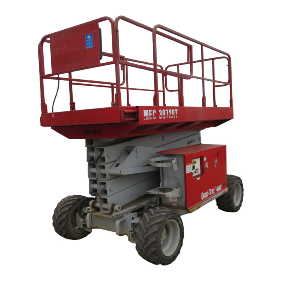
3072RT / 3772RT
Ph
177
one
: (55
Sel
5
Par
9)
ma
, Ca
Str
k
891
-24
eet
lifo
, Su
88
a
rni
ite
Fax
: (55
936
62
77
9)
891
-24
93
ART_2497
SERVICE AND PARTS MANUAL
3772RT HD
3772RT / 3772RT HD: 9301000 - Present
Pho
177
ne:
(55
Sel
5
Par
9)
ma
891
, Cal
Str
k
-24
eet
ifor
, Sui
88
Fax
nia
936
te
77
: (55
62
891
9)
-24
93
Serial Number Range
3072RT: 9201000 - Present
Part # 91220 R1
March 2008

Advertisement

Table of Contents
loading
Need help?

Need help?

Do you have a question about the 3072RT and is the answer not in the manual?

Questions and answers

Subscribe to Our Youtube Channel

Summary of Contents for Mec 3072RT

  • Page 1 3072RT / 3772RT 3772RT HD : (55 , Ca lifo , Su : (55 , Cal ifor , Sui : (55 ART_2497 Serial Number Range Part # 91220 R1 3072RT: 9201000 - Present March 2008 3772RT / 3772RT HD: 9301000 - Present...
  • Page 2 Page 6-34 New Illustration: Generator Option, Diesel Page 6-35 Update parts list to identify new part numbers Parts Section 7 Page 7-4 Update illustration: 3072RT Sides Page 7-5 Update parts list Page 7-6 Update illustration: 3072RT Ends Page 7-7 Update parts list...
  • Page 3: Table Of Contents

    Emergency Systems And Procedures ............. 1-15 Steering Circuit ....................1-16 Platform Lift Circuit ................... 1-18 Optional Outriggers ................... 1-20 Cylinder Repair ....................1-21 Hydraulic Manifold..................... 1-24 "3072RT / 3772RT / 3772RT HD" Service & Parts Manual - ANSI Specifications March 2008 Page i...
  • Page 4 Outrigger Function .................... 3-14 Outrigger Calibration ..................3-15 GP106 Outrigger Control Module Troubleshooting ......... 3-17 Outrigger Module GP106 LED Flash Codes ..........3-18 March 2008 "3072RT / 3772RT / 3772RT HD" Service & Parts Manual - ANSI Specifications Page ii...
  • Page 5 Optional Outriggers Hydraulic Manifold ............5-5 Electric Schematics ..................... 5-6 Circuit Board ....................5-8 Controls ......................5-10 Engine ......................5-13 Optional Outriggers ..................5-15 Optional Generator ..................5-16 "3072RT / 3772RT / 3772RT HD" Service & Parts Manual - ANSI Specifications March 2008 Page iii...
  • Page 6 SECTION 1: CONTROL BOXES SECTION 2: PLATFORM AND RAILS SECTION 3: SCISSORS SECTION 4: AXLES SECTION 5: HYDRAULICS SECTION 6: BASE SECTION 7: DECALS March 2008 "3072RT / 3772RT / 3772RT HD" Service & Parts Manual - ANSI Specifications Page iv...
  • Page 7: Introduction

    We recommend that you use Genuine MEC parts to insure proper OPERATION and reliable PERFORMANCE. To obtain maximum benefits from your MEC scissors lift, always follow the proper operating and maintenance procedures. Only trained authorized personnel should be allowed to operate or service this machine.
  • Page 8 Any procedures not found within this manual must be evaluated by the individual to assure one- self that they are “proper and safe.” Your MEC Scissors Lift has been designed, built, and tested to provide many years of safe, de- pendable service. Only trained, authorized personnel should be allowed to operate or service the machine.
  • Page 9: General Safety Tips

    Watch for makeshift “fixes” which can jeopardize • safety as well as lead to more costly repair. 3772RT "3072RT / 3772RT / 3772RT HD" Service & Parts Manual - ANSI Specifications March 2008 Page III...
  • Page 10: Hydraulic System

    Any defect shall be repaired prior to continued use of the scissors lift. Inspection and maintenance should be performed by qualified personnel familiar with the equipment. March 2008 "3072RT / 3772RT / 3772RT HD" Service & Parts Manual - ANSI Specifications Page IV...
  • Page 11: Machine Specifications

    Meets requirements of ANSI A92.6-2006 Section 4. *Working height adds 6 feet (2 m) to platform height. **Weight may increase with certain options or country standards. "3072RT / 3772RT / 3772RT HD" Service & Parts Manual - ANSI Specifications March 2008 Page V...
  • Page 12 Power Module Upper Controls Maintenance 3772RT HD Lock Lift Assembly 3072RT Control Module Liquid Propane Liquid Propane (Dual Fuel Option) (Dual Fuel Option) Front March 2008 "3072RT / 3772RT / 3772RT HD" Service & Parts Manual - ANSI Specifications Page VI...
  • Page 13: Primary Machine Components

    3 | 4 | 5 Hydraulic Pump 1 | 3 | 4 | 5 Hydraulic reservoir intro | 1 Hydraulic Filter intro | 1 "3072RT / 3772RT / 3772RT HD" Service & Parts Manual - ANSI Specifications March 2008 Page VII...
  • Page 14: Lubrication

    Lithium N.L.G. #2 EP Monthly or Every 25 Hours, Purge Old Grease Whichever Occurs First Drain Plug REAR FRONT Zerk Fittings Zerk Fittings X72-Lube March 2008 "3072RT / 3772RT / 3772RT HD" Service & Parts Manual - ANSI Specifications Page VIII...
  • Page 15: Hydraulic System

    Emergency Systems And Procedures ......................1-15 Steering Circuit ............................1-16 Platform Lift Circuit ............................1-18 Optional Outriggers ............................1-20 Cylinder Repair ............................1-21 Hydraulic Manifold ............................1-24 "3072RT / 3772RT / 3772RT HD" Service & Parts Manual - ANSI Specifications March 2008 Page 1-1...
  • Page 16: Hydraulic System - General

    March 2008 "3072RT / 3772RT / 3772RT HD" Service & Parts Manual - ANSI Specifications Page 1-2...
  • Page 17: Hydraulic Fluid

    HYDRAULIC FLUID UNDER PRESSURE CAN PENETRATE AND BURN SKIN, DAMAGE EYES, AND MAY CAUSE SERIOUS INJURY OR BLINDNESS. FLUID LEAKS UNDER PRESSURE MAY NOT ALWAYS BE VISIBLE. "3072RT / 3772RT / 3772RT HD" Service & Parts Manual - ANSI Specifications March 2008 Page 1-3...
  • Page 18 Fluid Recommendations MEC recommends the use of Mobil 424 hydraulic fluid. Do not substitute with lower grade oils as pump damage may result. Hydraulic Fluid Analysis Use the following as a guide to determine when analysis of the hydraulic fluid is necessary: •...
  • Page 19 NOTE: AVOID MIXING PETROLEUM AND SYNTHETIC BASE OILS. IT IS NOT ADVISABLE TO MIX OILS OF DIFFERENT BRANDS OR TYPES, EXCEPT AS RECOMMENDED. "3072RT / 3772RT / 3772RT HD" Service & Parts Manual - ANSI Specifications March 2008 Page 1-5...
  • Page 20: Hydraulic Fluid Reservoir

    ( 6) months or 500 hours. Extremely dirty conditions may require that the filter be replaced more often. BEWARE OF HOT OIL. CONTACT WITH HOT OIL MAY CAUSE SEVERE BURNS. Filler Cap Sight Gauge Filter Element Drain Plug ART_X72-Lube1 March 2008 "3072RT / 3772RT / 3772RT HD" Service & Parts Manual - ANSI Specifications Page 1-6...
  • Page 21: Hydraulic Pump

    A fixed orifice in the brake circuit controls the deceleration rate and initiates a smooth stop. "3072RT / 3772RT / 3772RT HD" Service & Parts Manual - ANSI Specifications March 2008...
  • Page 22 2. Remove the seven (7) bolts that hold the motor assembly together. • Carefully remove the endcover - be aware that the piston and spring may fall out . March 2008 "3072RT / 3772RT / 3772RT HD" Service & Parts Manual - ANSI Specifications Page 1-8...
  • Page 23 • Tighten bolts in sequence (see illustration) • Pre-torque to 10 ft. lbs. (13,6 Nm). • Final torque to 50 ft. lbs (67,8 Nm). "3072RT / 3772RT / 3772RT HD" Service & Parts Manual - ANSI Specifications March 2008 Page 1-9...
  • Page 24 20. Divider Plate 31. Shaft Nut 10. * O-Ring Seal 21. Rotor Assembly 11. * Backup Seal 22. Manifold * Contained in seal kit March 2008 "3072RT / 3772RT / 3772RT HD" Service & Parts Manual - ANSI Specifications Page 1-10...
  • Page 25 • Alternate disk stampings and friction disks until all disks except the thick disk stamping are installed. • Install the thick disk stamping on top of the disk assembly. "3072RT / 3772RT / 3772RT HD" Service & Parts Manual - ANSI Specifications March 2008 Page 1-11...
  • Page 26 • Tighten bolts in sequence (see illustration) • Pre-torque to 10 ft. lbs (13,6 Nm). • Final torque to 50 ft. lbs (67,8 Nm). March 2008 "3072RT / 3772RT / 3772RT HD" Service & Parts Manual - ANSI Specifications Page 1-12...
  • Page 27 16. Shaft Bearing 35. Shaft 17. Friction Disks (10) 36. Shaft Key 18. Disk Stampings (9) 37. Shaft Nut 19. Thick Disk Stampings (2) "3072RT / 3772RT / 3772RT HD" Service & Parts Manual - ANSI Specifications March 2008 Page 1-13...
  • Page 28: Parking Brake And Towing Circuit

    To Reset Brakes: • Brakes will reset when drive function is activated, or reset manually by pulling out the manual brake release valve. March 2008 "3072RT / 3772RT / 3772RT HD" Service & Parts Manual - ANSI Specifications Page 1-14...
  • Page 29: Emergency Systems And Procedures

    2. Once the platform is fully lowered, release the toggle switch to close the valve Emergency Lowering Switch "3072RT / 3772RT / 3772RT HD" Service & Parts Manual - ANSI Specifications March 2008 Page 1-15...
  • Page 30: Steering Circuit

    Valves Steer Right Port Steer Left Steer Left GRN/RED Port Steer Right 4 Way-3 Position Solenoid ORG/WHT Operated Hydraulic Directional Control Cartridge Valve March 2008 "3072RT / 3772RT / 3772RT HD" Service & Parts Manual - ANSI Specifications Page 1-16...
  • Page 31 Steer Cylinder Tie Rod Motor Wheel Motor Housing Pivot Motor Motor Housing Housing Pivot "3072RT / 3772RT / 3772RT HD" Service & Parts Manual - ANSI Specifications March 2008 Page 1-17...
  • Page 32: Platform Lift Circuit

    Lift Counterbalance RED/BLU Valves 3 Way Solenoid Operated Hydraulic Spool Valve March 2008 "3072RT / 3772RT / 3772RT HD" Service & Parts Manual - ANSI Specifications Page 1-18...
  • Page 33 Down Valve LOWER LIFT CYLINDER WITH BEARINGS Orifice Emergency Down Cable Pressure Hose Pressure Sensor Cylinder Valve Manifold 3072RT LIFT CYLINDER WITH BEARINGS "3072RT / 3772RT / 3772RT HD" Service & Parts Manual - ANSI Specifications March 2008 Page 1-19...
  • Page 34: Optional Outriggers

    Outrigger Retract Stowed Valve Switch (UP) Outrigger Pressure Switch Outrigger (DOWN) Extend FRONT Valve LEFT RIGHT BACK PORT ORLS PORT ORS PORT ORR March 2008 "3072RT / 3772RT / 3772RT HD" Service & Parts Manual - ANSI Specifications Page 1-20...
  • Page 35: Cylinder Repair

    2. Disconnect hoses and IMMEDIATELY cap the openings to prevent contamination. 3. Remove cylinder from the machine as described in Section 3 . "3072RT / 3772RT / 3772RT HD" Service & Parts Manual - ANSI Specifications March 2008 Page 1-21...
  • Page 36 Polishing is a sign of uneven loading. Check for roundness. If a polished surface is not round within .007 in. (0,18 mm) replace the cylinder. March 2008 "3072RT / 3772RT / 3772RT HD" Service & Parts Manual - ANSI Specifications Page 1-22...
  • Page 37 NOTE: It is very important to keep all parts clean when working with hydraulic cylinders, even one small piece of dirt or grit can damage the cylinder. "3072RT / 3772RT / 3772RT HD" Service & Parts Manual - ANSI Specifications March 2008...
  • Page 38: Hydraulic Manifold

    3. Connect hydraulic hoses (as previously tagged). Be certain to tighten hoses. 4. Connect the battery. 5. Operate each hydraulic function and check for proper operation and leaks. 6. Adjust valve pressures. March 2008 "3072RT / 3772RT / 3772RT HD" Service & Parts Manual - ANSI Specifications Page 1-24...
  • Page 39 PROPORTIONAL MANUAL VALVE 333 - PPL/WHT FOR BRAKE RELEASE LIFT PORT STEER RIGHT STEER LEFT PRESSURE PORT LEFT RIGHT - FROM PUMP - "3072RT / 3772RT / 3772RT HD" Service & Parts Manual - ANSI Specifications March 2008 Page 1-25...
  • Page 40 March 2008 "3072RT / 3772RT / 3772RT HD" Service & Parts Manual - ANSI Specifications Page 1-26...
  • Page 41: Electrical System

    Alarms and Switches ............................2-7 Tilt Alarm ................................ 2-8 Relays ................................2-9 Limit Switch ..............................2-10 Optional Outriggers Switches ......................... 2-10 Continuity Checks ............................2-11 "3072RT / 3772RT / 3772RT HD" Service & Parts Manual - ANSI Specifications March 2008 Page 2-1...
  • Page 42: Electrical System - General

    The control system for operation of drive/steer and lift/lower are electric-over-hydraulic type. The drive system is a proportional system controlled by position and direction of the upper control box controller handle (joystick). March 2008 "3072RT / 3772RT / 3772RT HD" Service & Parts Manual - ANSI Specifications Page 2-2...
  • Page 43: Deutsch Connectors

    • Close the handles of the crimping tool, then release the handles to remove the crimped contact. "3072RT / 3772RT / 3772RT HD" Service & Parts Manual - ANSI Specifications March 2008 Page 2-3...
  • Page 44: Battery

    - drops to 40% at 0°F (-32°C) Recommended Intervals If Stored At: Recharge: Below 40°F (4°C) None required Above 60°F (15°C) Every month 40°-60°F (4°-15°C) Every 2 months March 2008 "3072RT / 3772RT / 3772RT HD" Service & Parts Manual - ANSI Specifications Page 2-4...
  • Page 45: Battery Preventative Maintenance

    Battery Specific Gravity and Voltage Table SPECIFIC GRAVITY VOLTS DC EACH CELL PER CELL 12V BATTERY Fully Charged 1.280 2.10 12.60 Fully Discharged 1.130 1.75 10.50 "3072RT / 3772RT / 3772RT HD" Service & Parts Manual - ANSI Specifications March 2008 Page 2-5...
  • Page 46: Battery Replacement

    To install battery, reverse the process by positioning the battery in the compartment securely with hold down bolts. Connect battery cables. Always connect the positive cable first. March 2008 "3072RT / 3772RT / 3772RT HD" Service & Parts Manual - ANSI Specifications Page 2-6...
  • Page 47: Alarms And Switches

    When the LED is ON the func- tion is ENERGIZED. Refer to the DIAG- NOSTIC LED’S label to identify the LED function. "3072RT / 3772RT / 3772RT HD" Service & Parts Manual - ANSI Specifications March 2008 Page 2-7...
  • Page 48: Tilt Alarm

    THE MOVEMENT ALARM IS PROVIDED FOR YOUR PROTECTION, AND PROTECTION OF PERSONS WORKING IN THE IMMEDIATE AREA. DISABLING THIS IMPORTANT SAFETY DEVICE MAY RESULT IN SERIOUS INJURY OR DEATH. March 2008 "3072RT / 3772RT / 3772RT HD" Service & Parts Manual - ANSI Specifications Page 2-8...
  • Page 49: Relays

    Purpose: The diesel engine glow plug receives its power through the Glow Plug Relay. Throttle Solenoid Throttle Relay Power Module Glow Plug Relay (Diesel only) "3072RT / 3772RT / 3772RT HD" Service & Parts Manual - ANSI Specifications March 2008 Page 2-9...
  • Page 50: Limit Switch

    Stowed Switches open and lift function is disabled. When all four (4) outriggers reach full deployment the Outrigger Pres- sure Switches close (engage) and lift function is restored. March 2008 "3072RT / 3772RT / 3772RT HD" Service & Parts Manual - ANSI Specifications Page 2-10...
  • Page 51: Continuity Checks

    SWITCH DEPRESSED A - B OPEN C - D OPEN Plunger E - F CLOSED ART_2331 "3072RT / 3772RT / 3772RT HD" Service & Parts Manual - ANSI Specifications March 2008 Page 2-11...
  • Page 52 March 2008 "3072RT / 3772RT / 3772RT HD" Service & Parts Manual - ANSI Specifications Page 2-12...
  • Page 53: Mechanical Components

    Outrigger Function ............................3-14 Outrigger Calibration ............................ 3-15 GP106 Outrigger Control Module Troubleshooting ..................3-17 Outrigger Module GP106 LED Flash Codes ....................3-18 "3072RT / 3772RT / 3772RT HD" Service & Parts Manual - ANSI Specifications March 2008 Page 3-1...
  • Page 54: Torque Specifications

    950 - 1050 107 - 119 130 - 140 176 - 190 130 - 140 176 - 190 1300 - 1368 147 - 155 March 2008 "3072RT / 3772RT / 3772RT HD" Service & Parts Manual - ANSI Specifications Page 3-2...
  • Page 55: Mechanical Components

    1. Tighten lugs to proper torque (refer to machine specifications). 2. Raise machine slightly and remove jack stands. 3. Lower the machine and remove the jack. 4. Remove chocks. "3072RT / 3772RT / 3772RT HD" Service & Parts Manual - ANSI Specifications March 2008 Page 3-3...
  • Page 56: Tires

    3. Install the replacement wheel. 4. Fasten lug nuts and tighten to proper torque. (Refer to machine specifications) 5. Lower the machine and remove the chocks. March 2008 "3072RT / 3772RT / 3772RT HD" Service & Parts Manual - ANSI Specifications Page 3-4...
  • Page 57: Drive Motors

    5. Remove the cap screws and remove the drive motor from the MOTOR HOUSING housing. Replace DRIVE Installation is reverse of removal. MOTOR MOTOR "3072RT / 3772RT / 3772RT HD" Service & Parts Manual - ANSI Specifications March 2008 Page 3-5...
  • Page 58: Steer Cylinder

    Steer Cylinder Seal Replacement Refer to Section 1 for seal replacement instructions. Steer Cylinder Tie Rod Motor Wheel Motor Housing Pivot Motor Motor Housing Housing Pivot March 2008 "3072RT / 3772RT / 3772RT HD" Service & Parts Manual - ANSI Specifications Page 3-6...
  • Page 59: Hoses And Cables

    3. Remove the bolts from both platform brackets at the rear of the machine. 4. Slide platform and roll out deck off the machine. EV108 "3072RT / 3772RT / 3772RT HD" Service & Parts Manual - ANSI Specifications March 2008 Page 3-7...
  • Page 60: Lift Cylinder Removal And Installation

    1. Remove the platform and lift cylinder(s). 2. Attach a suitable lifting device ti the scissor assembly. 3. Lift the scissor assembly Installation is reverse of removal. March 2008 "3072RT / 3772RT / 3772RT HD" Service & Parts Manual - ANSI Specifications Page 3-8...
  • Page 61: Engine Maintenance

    Under Cabinet 4. Replace the canister and attach the hoses. Tighten the canister bracket and hose clamps. Air Filter Canister Air Filter Element "3072RT / 3772RT / 3772RT HD" Service & Parts Manual - ANSI Specifications March 2008 Page 3-9...
  • Page 62 5. Turn off the engine and reconnect the Throttle Solenoid linkage at the clevis. 6. Hold the High Speed Stop Screw while tightening the jam nut to prevent change in adjustment. March 2008 "3072RT / 3772RT / 3772RT HD" Service & Parts Manual - ANSI Specifications Page 3-10...
  • Page 63 • Reconnect the clevis and measure again. Repeat until the measurement is correct. High Speed Stop Screw .020 Throttle Solenoid Idle Stop Screw Throttle Lever Clevis Throttle Solenoid Piston (Threaded Rod) Throttle Solenoid Adjustment "3072RT / 3772RT / 3772RT HD" Service & Parts Manual - ANSI Specifications March 2008 Page 3-11...
  • Page 64: Gasoline And Dual Fuel Engine

    Recovery Tank 5. Reposition and tighten the hose clamps. 6. Open valve at fuel tank and check for leaks. Oil Drain Access Under Cabinet March 2008 "3072RT / 3772RT / 3772RT HD" Service & Parts Manual - ANSI Specifications Page 3-12...
  • Page 65 4. Adjust the nuts on the Throttle Solenoid Piston until the engine RPM is 3850±50. 5. Tighten the nuts to secure the adjustment. "3072RT / 3772RT / 3772RT HD" Service & Parts Manual - ANSI Specifications March 2008 Page 3-13...
  • Page 66: Outrigger Function

    OUTRIGGER FUNCTION The outriggers on the RT series MEC Scissor Lifts are a One-Touch Activation system. To deploy the outriggers, simply push the outrigger toggle switch down until the outriggers level the unit and the engine returns to idle. You are now ready to lift the platform. The outrigger control module is a “smart”...
  • Page 67: Outrigger Calibration

    Before attempting the calibration procedure, move the machine to an area that is level as mea- sured by a spirit level or other leveling device. An EZ-Cal hand-held device (MEC part # 90888) is required to carry out all calibration procedures on the GP106 Outrigger Control Module.
  • Page 68 Press Enter. Display reads TILT 0.0’,0.0’ h. Press ESC, ESC i. Disconnect EZ-Cal from the outrigger control module. Outrigger calibration is now complete. March 2008 "3072RT / 3772RT / 3772RT HD" Service & Parts Manual - ANSI Specifications Page 3-16...
  • Page 69: Gp106 Outrigger Control Module Troubleshooting

    OUTRIGGER WIRING FAULT The system has detected voltage on P2-2 but voltage is not present on P2-5 or P2-6. Check wiring to P2-5/6. "3072RT / 3772RT / 3772RT HD" Service & Parts Manual - ANSI Specifications March 2008 Page 3-17...
  • Page 70: Outrigger Module Gp106 Led Flash Codes

    This indicates that the machine is not level. It is not a fault and will not affect operation of outriggers. LED flash code 9 This indicates that the GP106 is performing startup tests. March 2008 "3072RT / 3772RT / 3772RT HD" Service & Parts Manual - ANSI Specifications Page 3-18...
  • Page 71: Troubleshooting

    General Troubleshooting Tips .................... 4-3 Common Causes of Hydraulic System Malfunctions: ............4-3 Hydraulic Pressure Adjustment Procedures ..............4-9 Proportional Speed Adjustment..................4-12 Controls and Switches ......................4-14 "3072RT / 3772RT / 3772RT HD" Service & Parts Manual - ANSI Specifications March 2008 Page 4-1...
  • Page 72 LIFT RELIEF BRAKE PORT STEER RELIEF STEER RIGHT STEER LEFT PULL VALVE BRAKE RELEASE PRESSURE PORT LEFT RIGHT - TO PUMP - DIAGNOSTIC LEDs March 2008 "3072RT / 3772RT / 3772RT HD" Service & Parts Manual - ANSI Specifications Page 4-2...
  • Page 73: General Troubleshooting Tips

    TROUBLESHOOTING The 3072RT and 3772RT are designed for ease of diagnostics. There is a terminal strip located under the work platform for checking signals to and from Upper Controls. There are also LED’s located in the Lower Controls box to indicate outputs from the circuit board.
  • Page 74 Valve coil failed on either cylinder Test, replace Down valve on one cylinder inoperative Check valve coils, wiring Lowers but not completely continued… March 2008 "3072RT / 3772RT / 3772RT HD" Service & Parts Manual - ANSI Specifications Page 4-4...
  • Page 75 Check for 12 volts and ground to valve Check for faulty valve spool EP1 poppet valve not functioning Check or replace valve continued… "3072RT / 3772RT / 3772RT HD" Service & Parts Manual - ANSI Specifications March 2008 Page 4-5...
  • Page 76 Check switch in Joystick handle Steering Cylinder/s internal leakage Check for internal leakage - repair RV1 steer relief valve not functioning Check adjustment or replace continued… March 2008 "3072RT / 3772RT / 3772RT HD" Service & Parts Manual - ANSI Specifications Page 4-6...
  • Page 77 Check solenoid operation located in float bowl Faulty fuel pump Check power and ground at fuel pump during engine crank. Check fuel pump operation continued… "3072RT / 3772RT / 3772RT HD" Service & Parts Manual - ANSI Specifications March 2008 Page 4-7...
  • Page 78 Power on these wires should = 12 volts on ORG/BLU wire 224 Failed glow plugs Check for 12 volts at glow plugs while operating glow plugs. end Trouble Table March 2008 "3072RT / 3772RT / 3772RT HD" Service & Parts Manual - ANSI Specifications Page 4-8...
  • Page 79: Hydraulic Pressure Adjustment Procedures

    500-550 PSI 35-38 bar LEFT SIDE Gauge Port (Test Port) Main Relief Lift Relief Stand-By Pressure Relief Steer Relief Overpressure Relief PUMP LIFT CYLINDER MANIFOLD, 3772 "3072RT / 3772RT / 3772RT HD" Service & Parts Manual - ANSI Specifications March 2008 Page 4-9...
  • Page 80 Excessive flow will result in severe engine loading and stalling. Reduced flow will result in slower functions with no engine loading. If you suspect that the sitting is incorrect, please call MEC Product Support at (800) 387-4575 for assistance.
  • Page 81 4. Tighten the locknut while holding the adjustment screw in position to prevent it from rotating. 5. Repeat steps 1 through 4 on the other Counterbalance valve. 6. Adjustment is complete. Counterbalance Valves "3072RT / 3772RT / 3772RT HD" Service & Parts Manual - ANSI Specifications March 2008 Page 4-11...
  • Page 82: Proportional Speed Adjustment

    Speed Adjustment Table: 20 ft. (6 m) Course TRAVEL TIME TRIM POT IN SECONDS High Range 3.5 to 4.0 Low Range 27 to 33 March 2008 "3072RT / 3772RT / 3772RT HD" Service & Parts Manual - ANSI Specifications Page 4-12...
  • Page 83 Turn the RAMP trim pot clockwise until the slowest machine start-up can be achieved while maintaining good proportional ramp-up through the travel of the Joystick. "3072RT / 3772RT / 3772RT HD" Service & Parts Manual - ANSI Specifications March 2008...
  • Page 84: Controls And Switches

    Emergency Stop Lower (Green) Throttle Hour Meter (Green) Engine Stop Engine Start (Red) (Green) Choke/Preheat Platform / (Black) Chassis Circuit Breaker Gasoline/Propane (Dual Fuel) March 2008 "3072RT / 3772RT / 3772RT HD" Service & Parts Manual - ANSI Specifications Page 4-14...
  • Page 85: Schematics

    Optional Outriggers Hydraulic Manifold ................5-5 Electric Schematics ......................5-6 Circuit Board ........................5-8 Controls..........................5-10 Engine ..........................5-13 Optional Outriggers ......................5-15 Optional Generator ......................5-16 "3072RT / 3772RT / 3772RT HD" Service & Parts Manual - ANSI Specifications March 2008 Page 5-1...
  • Page 86: Hydraulic Schematic

    CYL1 Cylinder, Steering Optional Outriggers Components CYL5 Outrigger Cylinder Solenoid Valve, Poppet N.C. Solenoid Valve, Poppet N.C. Spool Valve, 4Way - 3 Position March 2008 "3072RT / 3772RT / 3772RT HD" Service & Parts Manual - ANSI Specifications Page 5-2...
  • Page 87 "3072RT / 3772RT / 3772RT HD" Service & Parts Manual - ANSI Specifications March 2008 Page 5-3...
  • Page 88: Main Hydraulic Manifold

    GSTR LEFT BOTTOM SVD1 PLG4 PLG4 PLG4 PLG4 ORLS PLG4 PLG4 FRONT BACK CBV1 OPL5 PLG4 PLG4 PLG4 PLG6 CBV2 MP1 OD1 RIGHT March 2008 "3072RT / 3772RT / 3772RT HD" Service & Parts Manual - ANSI Specifications Page 5-4...
  • Page 89: Optional Outriggers Hydraulic Manifold

    Optional Outriggers Hydraulic Manifold SV1 CL1 CL1 CAV1 PLG10 LEFT FRONT PLG4 ORLS RIGHT BOTTOM "3072RT / 3772RT / 3772RT HD" Service & Parts Manual - ANSI Specifications March 2008 Page 5-5...
  • Page 90: Electric Schematics

    ELECTRIC SCHEMATICS March 2008 "3072RT / 3772RT / 3772RT HD" Service & Parts Manual - ANSI Specifications Page 5-6...
  • Page 91 TILT SENSOR "3072RT / 3772RT / 3772RT HD" Service & Parts Manual - ANSI Specifications March 2008 Page 5-7...
  • Page 92: Circuit Board

    The Circuit Bard schematic is broken into two pages for clarity. The cable connections are shown on this page. Match the numbers to line-up the traces. March 2008 "3072RT / 3772RT / 3772RT HD" Service & Parts Manual - ANSI Specifications Page 5-8...
  • Page 93 "3072RT / 3772RT / 3772RT HD" Service & Parts Manual - ANSI Specifications March 2008 Page 5-9...
  • Page 94: Controls

    Controls March 2008 "3072RT / 3772RT / 3772RT HD" Service & Parts Manual - ANSI Specifications Page 5-10...
  • Page 95 "3072RT / 3772RT / 3772RT HD" Service & Parts Manual - ANSI Specifications March 2008 Page 5-11...
  • Page 96 March 2008 "3072RT / 3772RT / 3772RT HD" Service & Parts Manual - ANSI Specifications Page 5-12...
  • Page 97: Engine

    Engine "3072RT / 3772RT / 3772RT HD" Service & Parts Manual - ANSI Specifications March 2008 Page 5-13...
  • Page 98 March 2008 "3072RT / 3772RT / 3772RT HD" Service & Parts Manual - ANSI Specifications Page 5-14...
  • Page 99: Optional Outriggers

    B+ (VCC1) RED/WHT 201 RELAY ALARM TERMINAL BLK 15 THROTTLE SWITCH ORG/BLU 125 TERMINAL 4 BLK/ORG 125 PCB TERMINAL S5 LOWER CONTROL BOX "3072RT / 3772RT / 3772RT HD" Service & Parts Manual - ANSI Specifications March 2008 Page 5-15...
  • Page 100: Optional Generator

    ENGINE HARNESS PIN 2 HARNESS PIN 12 PIN 12 CIRCUIT POWER PIN 5 PIN 5 BOARD MODULE ORG/WHT PIN 3 CONTROL MODULE GENERATOR March 2008 "3072RT / 3772RT / 3772RT HD" Service & Parts Manual - ANSI Specifications Page 5-16...

This manual is also suitable for:

3772rt3772rt hd

Table of Contents