Table of Contents
Advertisement
Available languages
Available languages
Quick Links
INSTRUCTION MANUAL CODE 80191 REV D JAN/2020
(It can be modified without notice)
Page: 1
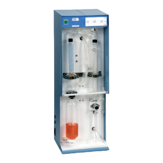
DESTILADOR ENOLÓGICO
ALCOHOL DISTILLATION UNIT
DE-1626
4001626
J
.P. SELECTA s.a.u.
Ctra. NII Km 585.1 Abrera 08630 (Barcelona) España
Tel 34 937 700 877 Fax 34 937 702 362
e-mail: selecta@jpselecta.es - website: http://www.jpselecta.es
Advertisement
Table of Contents

Related Manuals for J.P. SELECTA DE-1626


Summary of Contents for J.P. SELECTA DE-1626
- Page 1 INSTRUCTION MANUAL CODE 80191 REV D JAN/2020 (It can be modified without notice) Page: 1 DESTILADOR ENOLÓGICO ALCOHOL DISTILLATION UNIT DE-1626 4001626 .P. SELECTA s.a.u. Ctra. NII Km 585.1 Abrera 08630 (Barcelona) España Tel 34 937 700 877 Fax 34 937 702 362...
-
Page 2: Table Of Contents
MANUAL DE INSTRUCCIONES CODIGO 80191 REV D ENE/2020 (Sujetas a modificaciones sin previo aviso) Pag.: 2 Indice 1 Lista de embalaje y accesorios ........................3 2 Seguridad ..............................4 3 Introducción ..............................5 4 Instalación..............................6 5 Funcionamiento ............................7 6 Destilación de muestras ..........................9 7 Verificación del equipo (OQ) ........................10 8 Mantenimiento ............................11 9 Especificaciones técnicas ...........................12... -
Page 3: Lista De Embalaje Y Accesorios
INSTRUCTION MANUAL CODE 80191 REV D JAN/2020 (It can be modified without notice) Page: 3 1 Lista de embalaje y accesorios 1.1 Contenido estándar del paquete • Equipo destilador • Tubo 1.5m entrada de agua. Alta presión, conexión de 3/8’’. • Tubo 1.5m salida de agua. Silicona 8x14, conexión de 3/8’’. • Tubo 1.5m vapor sobrante. Silicona 8x14, conexión de 3/8’’. • Tubo 1.5m vaciado generador. Silicona 8x14. • Tubo 1.5m deposito agua. -
Page 4: Seguridad
MANUAL DE INSTRUCCIONES CODIGO 80191 REV D ENE/2020 (Sujetas a modificaciones sin previo aviso) Pag.: 4 2 Seguridad El destilador enológico DE-1626 incluye las medidas de seguridad adecuadas para su utilización en un laboratorio. Sin embargo, su utilización conlleva unos riesgos que deben ser conocidos por el operador. En este manual se indican las situaciones de riesgo que deben respetarse. 2.1 Iconos de seguridad Identifican las situaciones de riesgo y las medidas de seguridad que deben tomarse. Los iconos hacen referencia al párrafo marcado con la línea gris. Riesgo de peligro Riesgo de peligro. Respetar las instrucciones indicadas para realizar la operación descrita. Riesgo eléctrico Riesgo de accidente eléctrico al acceder a las zonas indicadas con esta señal o al realizar las operaciones indicadas en este manual acompañadas de este icono. Respetar las instrucciones indicadas para realizar la operación descrita. Riesgo de quemaduras por contacto con zonas a temperatura elevada La temperatura en la zona indicada con este icono puede exceder los 60ºC. Utilizar guantes... -
Page 5: Introducción
INSTRUCTION MANUAL CODE 80191 REV D JAN/2020 (It can be modified without notice) Page: 5 3 Introducción El equipo DE-1626 es un destilador por arrastre de vapor para la obtención del des- tilado de bebidas alcohólicas. El equipo está validado de acuerdo al reglamento CEE nº 2676/90 (análisis de vinos) y CEE Nº 2870/2000 (análisis de bebidas espirituosas) para la determinación del grado alcohólico. Proporciona una destilación por arrastre de vapor muy rápida y una eficiente extracción de los componentes volátiles (alcoholes y ácidos acético). Dado que DE-1626 está, fundamentalmente, destinado a la determinación del grado alcohólico, esta se describe con precisión en el capítulo 11. En los capítulos 5 y 6 se expone el funcionamiento general del equipo y como obtener el destilado de una muestra. El equipo se compone de los siguientes sistemas: El generador de vapor Genera vapor a partir del agua del deposito situado en el exterior del equipo. El generador de vapor incluye un Termostato de seguridad que interrumpe el suministro eléctrico al generador de vapor en caso de que la temperatura aumente... -
Page 6: Instalación
Escoger una toma de corriente cercana al equipo y adecuada a la potencia del equipo. Utilizar el cable de conexión suministrado u otro de similares características. Para su seguridad, la toma de corriente debe tener conexión a tierra. Antes de enchufar, verificar que la tensión y frecuencia de la red eléctrica corresponde a la indicada en la etiqueta de características del equipo. 4.3 Conexiones a la red de agua y desagües Conectar la manguera de entrada de agua (1) a un grifo y la salida del agua refrige- rante (2) a un desagüe. Las mangueras de «vapor sobrante» (3) y de «vaciado del generador de vapor» (4) deben ir al desagüe. No olvidar poner las juntas en las conexiones de plástico. Apretar con la mano. No utilizar ninguna herramienta. La presión mínima de la red debe ser 1 bar. El grifo puede dejarse siempre abierto, el DE-1626 dispone de una válvula que abre y cierra el paso de agua automáticamente. Nota: Es importante para el correcto funcionamiento del equipo que el extremo libre de la manguera «Vapor sobrante» (3) NO esté sumergido en el agua, ni doblado de forma que pueda quedar obturado. 4.4 Agua para el generador de vapor El equipo lleva incorporado un depósito con capacidad de unos 2 litros para almacenar el agua que utiliza el generador de vapor. Dado que el sistema de control de nivel de agua del generador de vapor funciona por conductividad, debe utilizarse con una conductividad mínima de 20 microSiemens y sin exceso de cal, para alargar la vida del generador de vapor. Puede obtenerse agua de estas características, directamente de un equipo de agua desmineralizada. -
Page 7: Funcionamiento
INSTRUCTION MANUAL CODE 80191 REV D JAN/2020 (It can be modified without notice) Page: 7 5 Funcionamiento El panel de control permite seleccionar las funciones del equipo e informa del estado actual de funcionamiento y de las alarmas. Una vez enchufado a red, pulsando el interruptor principal, el equipo se pone en marcha (ON). Nota: Si se pulsa el interruptor principal de forma consecutiva con un intervalo de menos de 3 segundos, puede ser que el equipo no se ponga en marcha correctamente. Al poner en marcha el equipo por primera vez, la bomba de agua empieza a funcionar, de forma automática, para llenar el generador de vapor. Esta operación suele durar unos 40 segundos hasta detenerse también de forma automática. A los 20 seg. suena una alarma que debe pararse por si sola. (Si la alarma se dispara, el equipo queda bloqueado. Parar y poner en marcha de nuevo mediante el interruptor principal.) Si no se detiene, compruebe que ha rellenado el depósito de agua, y que esta tiene la conductividad adecuada. (Ver 4.4) 5.1 Colocar/ Extraer el tubo muestra ATENCIÓN • Colocar el tubo muestra empezando por introducir el tubo de teflón . • Seguidamente, bajar la palanca de fijación. Utilice guantes antitérmicos. - Page 8 Para evitar situaciones de peligro para el usuario o para proteger la vida del equipo se han incorporado unos sistema de seguridad y unas situaciones de alarma: (1) Alarma falta de agua en el generador de vapor • El piloto se ilumina esporádicamente: indica que el control de nivel detecta un nivel bajo de agua y automáticamente pone en marcha la bomba. • El piloto se ilumina permanentemente: indica que el control de nivel detecta un nivel bajo de agua y no se llena de agua. Automáticamente el circuito de control interrumpe la destilación. Probablemente el depósito de agua está vacío, o hay algún problema en la bomba de alimentación de agua. La alarma bloquea el funcionamiento. Parar y reiniciar el DE-1626. (2) Indicador de estado del destilador Este piloto amarillo indica que el circuito de destilación está activado. (3) Alarma de exceso de temperatura Este piloto rojo permanece iluminado cuando un exceso de temperatura en el gene- rador de vapor ha disparado el termostato de seguridad. Bloquea la función de destilación. Una vez disparado, se debe dejar enfriar, solucionar la causa que lo ha provocado y rearmar el termostato pulsando el botón central. El termostato de seguridad se encuentra en el cuadro eléctrico. Para acceder a él debe desmontar la tapa derecha del equipo.
-
Page 9: Destilación De Muestras
INSTRUCTION MANUAL CODE 80191 REV D JAN/2020 (It can be modified without notice) Page: 9 6 Destilación de muestras Para obtener el destilado con el máximo contenido de alcohol o sustancias volátiles y obtener un buen comportamiento del equipo conviene seguir la siguiente rutina de trabajo. Una vez obtenido el destilado medir el %Vol o la acidez volátil. Ver Capítulos 11 y 12. 6.1 Revisar el nivel del depósito de agua Rellenarlo con agua desmineralizada o destilada y añadir 5 mg/l de Cloruro Sódico para conseguir una conductividad mínima de unos 20 microSiemens.cm 6.2 Precalentamiento del equipo Para asegurar que el equipo proporcione su máxima eficiencia en la destilación, con- viene que antes iniciar una sesión de análisis esté a su temperatura de régimen. Para ello insertar un tubo muestra con unos 25ml de agua limpia y recoger el destilado durante 5 minutos. -
Page 10: Verificación Del Equipo (Oq)
MANUAL DE INSTRUCCIONES CODIGO 80191 REV D ENE/2020 (Sujetas a modificaciones sin previo aviso) Pag.: 10 7 Verificación del equipo (OQ) Una vez instalado y conocido su funcionamiento, es necesario verificarlo. 7.1 Verificación funcional Realizar está verificación en el momento de la instalación y diariamente para preca- lentar el equipo. Seguir las instrucciones del capítulo 5 para destilar durante unos 5 minutos. Cuando el equipo está a régimen de temperatura destila a razón de unos 30 - 40 ml por minuto. 7.2 Verificación de la perdida de etanol Esta verificación es ampliamente utilizada para certificar el funcionamiento del des- tilador. Antes de analizar muestras valiosas, realizar algunas practicas con soluciones hidroal- cohólicas para familiarizarse con el equipo. -
Page 11: Mantenimiento
INSTRUCTION MANUAL CODE 80191 REV D JAN/2020 (It can be modified without notice) Page: 11 8 Mantenimiento El destilador DE-1626 necesita un mantenimiento mínimo. Realizar inspecciones visuales en el interior para localizar posibles perdidas de líquido o vapor en juntas, conexiones de tubos, mangueras, etc. Para evitar la corrosión del equipo, secar cualquier derrame accidental en las partes metálicas de equipo y mantener una limpieza adecuada. 8.1 Limpieza del equipo 8.1.1 Limpieza del circuito de destilación Después de cada sesión de análisis, destilar unos 50ml de agua destilada durante... -
Page 12: Especificaciones Técnicas
MANUAL DE INSTRUCCIONES CODIGO 80191 REV D ENE/2020 (Sujetas a modificaciones sin previo aviso) Pag.: 12 9 Especificaciones técnicas Voltaje de red: 230V 50/60Hz (Ver etiqueta de características) Otros Voltajes de red están disponibles (Consultar) Potencia eléctrica total: 2450W (Ver etiqueta de características) Potencia de generador de vapor: 2400W. Intensidad máxima: 11 A Fusibles: 15 A rápido. dimensiones: 20x5 mm Cable de conexión a red: Fase, Neutro, Tierra (sección 1mm Peso (Neto): 35 Kg Medidas: Fondo x Ancho x Alto 300 x 300 x 900 mm Volumen depósito agua: 2 litros Consumo de agua del generador de vapor: entre 1 y 1.25 ml por ml de destilado obtenido. -
Page 13: Servicio Técnico
A continuación se ofrece una lista de recambios para facilitar su adquisición e iden- tificación. 10.1 Piezas de recambio 16087 Electroválvula N. A. 16067 Electroválvula de entrada de agua. 16025 Electroválvula de PINZA 24278 Bomba Agua. 28129 Goma de cierre. 28061 Bandeja recolectora de gotas. 32050 Generador de vapor 2400W. 47043 Refrigerante DE-1626 28129 47044 Rectificador DE-1626. 47045 Tubo de unión DE-1626. 47259 Válvula antiretorno. 29520 Placa electrónica de relés. 29511 Placa electrónica del panel de mandos. Mangueras: 46030 Tubo sumergido en la muestra TUBO TEFLON 8X10MM 46041 Tubo silicona 8x14 Para agua y vapor. -
Page 14: Grado Alcohólico Volumétrico
MANUAL DE INSTRUCCIONES CODIGO 80191 REV D ENE/2020 (Sujetas a modificaciones sin previo aviso) Pag.: 14 11 Grado alcohólico volumétrico 11.1 Alcoholímetro (aerometría) El grado alcohólico volumétrico se define como el nº de litros de etanol y sus ho- mólogos (metanol, alcoholes superiores, etc...) contenidos en 100 litros de vino (o bebida alcohólica en general), medidos ambos volúmenes a la temperatura de 20ºC. El principio de la determinación es sencillo: La muestra se alcaliniza, se destila y se mide el % de alcohol mediante unos aerómetros graduados de forma especial para este uso que reciben el nombre de alcoholímetros. Existen otros métodos para medir en contenido de alcohol en el destilado (balanza hidrostática, refractometro,...) pero el alcoholímetro es el que da más precisión y repetibilidad. - Page 15 INSTRUCTION MANUAL CODE 80191 REV D JAN/2020 (It can be modified without notice) Page: 15 11.1.4 Lectura del grado alcohólico con el alcoholímetro Medida con el alcoholímetro Es imprescindible que antes de realizar esta operación todo el material utilizado (matraz, alcoholímetros, probeta) haya estado almacenado a 20±0.5ºC. • Verter el destilado en la probeta de 250ml.
- Page 16 MANUAL DE INSTRUCCIONES CODIGO 80191 REV D ENE/2020 (Sujetas a modificaciones sin previo aviso) Pag.: 16 11.2 Balanza + Inmersor colgante 11.2.1 Material • Probeta de 100 ml • Inmersor con su tabla de conversión • Termómetro 0-35ºC resolución mínima 0.5ºC • Balanza electrónica 11.2.2 Procedimiento Antes de empezar, comprobar que la Tª ambiente está estable dentro de 20 ±3ºC y el líquido destilado dentro de 20±0.5ºC .
- Page 17 INSTRUCTION MANUAL CODE 80191 REV D JAN/2020 (It can be modified without notice) Page: 17 Tabla 2. Correspondencia entre el índice de refracción a 20ºC y el GAV Grados alcohólicos a 20ºC Grados alcohólicos a 20ºC Índice Índice de refracción Mezclas de refracción Mezclas Destilados Destilados a 20ºC hidroalcohólicas a 20ºC hidroalcohólicas 1,33628 6,54 6,48...
-
Page 18: Determinación De La Acidez Volátil
MANUAL DE INSTRUCCIONES CODIGO 80191 REV D ENE/2020 (Sujetas a modificaciones sin previo aviso) Pag.: 18 12 Determinación de la acidez volátil 12.1 Equipos Destilador DE-1626 Bureta para valoración Matraz kitasatos Trompa de vacío 12.2 Reactivos Solución saturada de bórax Yoduro potásico cristalizado Ácido clorhídrico (d = 1,8 ó 1,9 g/l) Ácido tartárico cristalizado Solución de hidróxido de sodio 0,05N Fenolftaleina 1% Solución de yodo 0,005 M ( 0,01N) Solución de engrudo de almidón 5g/l 12.3 Preparación de la muestra Eliminar el gas carbónico de la muestra colocándola en un Kitasatos y poniendo en... -
Page 19: Determinación Del Ácido Sórbico
INSTRUCTION MANUAL CODE 80191 REV D JAN/2020 (It can be modified without notice) Page: 19 13 Determinación del Ácido Sórbico Método de determinación por espectrofotometría de absorción en el ultravioleta. 13.1 Principio El ácido Sórbico separado por destilación con arrastre de vapor de agua se determina en el destilado mediante espectrofotometría de absorción ultravioleta. La sustancias que interfieren en la medida de la absorción en el ultravioleta se eliminan por evaporación a sequedad del destilado de la muestra, ligeramente alcalinizado por una solución de hidróxido de calcio. 13.2 Reactivos necesarios - Ácido tartárico cristalizado. - Solución de hidróxido de calcio Ca(OH) , aproximadamente 0.02M. - Solución de referencia de ácido Sórbico C de 20 mg por litro: Disolver 20 mg de ácido Sórbico en 2 ml. aproximadamente de solución 0.1M de hidróxido de sodio. Verter en un matraz aforado de 1000 ml, enrasar con agua. También pueden disolverse 26.8 mg de sorbato de potasio C en agua y completar con agua hasta 1000 ml. -
Page 20: Guía Para La Iq Y Oq
MANUAL DE INSTRUCCIONES CODIGO 80191 REV D ENE/2020 (Sujetas a modificaciones sin previo aviso) Pag.: 20 14 Guía para la IQ y OQ En algunos laboratorios se requiere que el instalador elabore un documento de IQ para certificar que la instalación del equipo se ha realizado correctamente y un do- cumento de OQ para certificar que el equipo funciona correctamente. El instalador puede elaborar estos documentos a partir de la siguiente listas de comprobación: 14.1 Lista de comprobación de la IQ (Instalation Qualification): • Nombre del instalador. • Nombre del fabricante: • Identificación del equipo: Código, modelo y número de serie. -
Page 21: Resolución De Problemas
INSTRUCTION MANUAL CODE 80191 REV D JAN/2020 (It can be modified without notice) Page: 21 16 Resolución de problemas • No se enciende el indicador verde del interruptor principal «ON» Verificar fusibles y cable de conexión a la red eléctrica. Verificar el interruptor principal. • El equipo está continuamente añadiendo agua hasta que esta sale por el tubo muestra El equipo no detecta el nivel de agua porque tiene poca conductividad. Añadir unos 250ml de agua del grifo al depósito de agua. -
Page 22: Packing List And Accessories
MANUAL DE INSTRUCCIONES CODIGO 80191 REV D ENE/2020 (Sujetas a modificaciones sin previo aviso) Pag.: 22 1 Packing list and accessories 1.1 Standard package content • Distillation unit • Tube 1.5m water input. 10 bar hose, connector 3/8’’. • Tube 1.5m water outlet. Silicone 8x14, connector 3/8’’. • Tube 1.5m remain steam. Silicone 8x14, connector 3/8’’. • Tube 1.5m boiler empty Silicone 8x14. (4) • Tube 1.5m water tank. -
Page 23: Safety
INSTRUCTION MANUAL CODE 80191 REV D JAN/2020 (It can be modified without notice) Page: 23 2 Safety The alcohol distillation unit DE-1626 has the suitable measures for its use in laboratory. However, working with it can be hazardous and the user must be informed of some of those risks. In order to be respected, the risk of danger situations are remarked across this manual. 2.1 Safety symbols It identifies the risky and safety actions to be applied. The symbols make reference to the paragraph marked with a grey line. Warning Warning of a dangerous operation. Indicated instruction must be followed. Hazard of electrical shock Electric hazard for entering in areas marked with this signal, or for following the manual instruction marked by this icon. Follow the instructions for the described operation. Hazard of burns to be in contact with hot surfaces Temperature in this area can exceed 60ºC. Use heat protected gloves for the described... -
Page 24: Overview
MANUAL DE INSTRUCCIONES CODIGO 80191 REV D ENE/2020 (Sujetas a modificaciones sin previo aviso) Pag.: 24 3 Overview The DE-1626 is a steam distillation, mainly designed to obtain the distillated from sample for later meassuring the %Vol (alcohol contents). The unit is validated accord- ing to CEE nº 2676/90 (wine analysis) and CEE Nº 2870/2000 (high degree drinks analysis) for alcohol degree determination. The DE-1626 yields a fast steam distillation and an efficient recovery of volatile sub- stances, as alcohol and acetic acid. As the DE-1626 will esentially be used for alcohol degree determination, this proce- dure is given in high detail on the chapter 11. Chapters 5 and 6 describe the general operation of the unit and how to obtain the distilled from samples. The unit has the following systems: The steam generator Generates steam from the water reservoir placed at the top of the unit. The steam generator includes a Safety thermostat that cuts the electrical power to the heater when overtemperature is detected on the steam generator (probably for poor level of water) and a pressure switch that cuts the electrical power to the heater, when there is an overpressure on the steam generator. Also includes a conductivity sensor to keep a constant level of water in the steam generator. -
Page 25: Installation
Use the power cord supplied or another of similar specification. For safety reason, the socket must have ground terminal, since the unit must work grounded. Before plugging on the socket, check that its voltage match the voltage marked on the unit plate. 4.3 Connection to tap water and waste Connect the water entry hose to a water tap (1). Connect the water output hose from (2) to waste. The hoses «remaining steam» (3) and «Steam generator empty» (4) must go to waste. Do not forget the rubber white nuts on the hose’s connections. Press plastic connections by hand. Do not use any tool. The tap water must have, at least, 1 bar pressure. Keep the tap opened. The DE-1626 will open / close the cooling water automatically. Note: It is critical in order that the unit works properly, the hose «Remaining steam» (3) MUST NOT BE IMMERSED under water, or blended or blocked by any reason. 4.4 Water for steam generator The unit includes a 2 litres water reservoir, at the top, to store the water for the steam generator. As the system used to control the level of water on the steam generator works by conductivity, water of at least 20 microSiemens must be used. Water , also, must have a low content of calcium to increase the life of the steam generator. Water with this conductivity could be obtained from a demineralised unit. Or from distilled water and add 5 mg/l Sodium Chloride. .P. SELECTA s.a.u. Ctra. NII Km 585.1 Abrera 08630 (Barcelona) España Tel 34 937 700 877 Fax 34 937 702 362 e-mail: selecta@jpselecta.es - website: http://www.jpselecta.es... -
Page 26: Operation
MANUAL DE INSTRUCCIONES CODIGO 80191 REV D ENE/2020 (Sujetas a modificaciones sin previo aviso) Pag.: 26 5 Operation The control panel allows function selection and shows the distiller alarms status Once the unit is plugged in, put it on, by pressing the main switch. The unit goes to stand by status (ON). Note: If main switch is pushed consecutively with an interval of less than 3 seconds, the unit could start in abnormal mode. So wait for a few seconds to restart the unit. On starting the unit for the first time, the water pump starts to work, automatically, to fill the steam generator. This operation usually takes near 40 seconds and it will stop when the steam generator is filled. Restart the unit if the alarm blocks it. If, after this 40 seconds, this operation is approx not finished, please check that the water tank (visual check on the right hand side level), and also check the water conductivity. (See 4.4) 5.1 Insert/ Remove the distillation tube... - Page 27 INSTRUCTION MANUAL CODE 80191 REV D JAN/2020 (It can be modified without notice) Page: 27 START 5.3 Distilling On pushing the «START» key, the unit starts sample distillation. This opens coolant water circuit and iniciates the steam generation. After 30s approx the sample starts to boil and its steams are driven to the cooler glassware for its condensation. The distilled is collected on the graduated flask or on the Erlenmeyer. When the level on the collected distilled will be near the sensor, the distillation will be stopped automatically and the outlet valve closed to avoid that the level exceeds the mark of the graduated flask. Approximately 180ml will be collected. Push the «STOP» key if you want to stop the sample distillation process. 5.4 Levelling The level sensor will stop the distillation approximately at 180 ml. Remove a little bit (see picture), the collector flask to add some drops of distilled to adjust up to near 200ml (an accurate adjust to 200ml must be done later when solution will be at 20ºC). On pushing «ADD» key, the outlet valve is opened to allow passing of some drops Placement for the collector flask to add of distilled from the cooler glassware. Push it some times to adjust the level near drops to near the graduated mark. the flask mark. Proceed similar with the Erlenmeyer flask. 5.5 Alarms To avoid dangerous situations for the operator or to protect the unit life, it includes some safety systems and some alarms: (1) Alarm: «No water for steam generator»...
-
Page 28: Sample Distillation
Please follow this steps: (on the same order) (see also chapter 11 for accurated details) • Visually check that the solenoid cooler is completely empty from rests of previous sample. If necessary, remove it on a separate flask by pushing «ADD» key. • Add near 10ml of distilled water on the collector flask. This is to avoid the loss of alcohol on the first condensed drops. • Place the collector flask on the flask holder. The flask wall must be in contact with the sensor face. The end of the tube from the cooler must be immersed under the level of the 10 ml of water. • Place the sample on the distillation tube and insert it on the DE-1626. • Push «START» key. • When the level of distilled obtained reaches the sensor face, the unit will stops distillation automatically. • First of all, remove the distillation tube. • Add distilled drops by pushing «ADD» key until levelling the collector flask. .P. SELECTA s.a.u. Ctra. NII Km 585.1 Abrera 08630 (Barcelona) España Tel 34 937 700 877 Fax 34 937 702 362... -
Page 29: Unit Verification (Oq)
INSTRUCTION MANUAL CODE 80191 REV D JAN/2020 (It can be modified without notice) Page: 29 7 Unit verification (OQ) Once the unit is installed and the operator trained with its operation, the unit could be qualified. This process could be used as a Operation qualification (OQ). There are two basic qualification operations: 7.1 Functional checking Run this operation during the installation steps and daily for unit warm-up. Follow chapter 5 instructions to distillate until the unit stops automatically (use Er- lenmeyer or graduated flask). When the unit is on the steady state, the distillation rate is between 30 - 40 ml per minute. 7.2 Checking the maximum etanol loss This checking is widely used to certify that the unit works properly. Run some of this tests for training purposes before analizing valuable samples. It consists on preparing some 10% dilution of distilled water and etanol. Prepare this solutions by using flask, and solutions at 20ºC and room temperature at 20±3ºC. -
Page 30: Maintenance
MANUAL DE INSTRUCCIONES CODIGO 80191 REV D ENE/2020 (Sujetas a modificaciones sin previo aviso) Pag.: 30 8 Maintenance The distillation unit DE-1626 needs a minimal maintenance operations. Run visual inspections inside to locate possible losses of liquid or steam on the joints, connec- tions, or hoses. To avoid metal parts corrosion, dry any occasional leakage of water inside the unit. 8.1 Cleaning the unit 8.1.1 Cleaning the distillation glassware Every day clean the distillation glassware after samples distillation. Just distillate 50ml of distilled water for 5 or 6 minutes. 8.1.2 Chamber cleaning The chamber and the drops collect tray must be cleaned every day just with a humid cloth and dried, to avoid deterioration. 8.2 Inspection of hoses (weekly) Visually check the hose condition and its connections to different components. To... -
Page 31: Technical Specification
INSTRUCTION MANUAL CODE 80191 REV D JAN/2020 (It can be modified without notice) Page: 31 9 Technical specification Mains voltage: 230V 50/60Hz (See plate Other power supply voltages could be available (Ask to your dealer) Electrical power: 2450W (See plate) Steam generator power: 2400W Maximum comsuption: 11 A Fuses: 15 A fast. dimensions: 20x5 mm Power supply cord: Phase, Neutral, Earth (section 1mm Weight (Net): 35 Kg Dimensions: W x L x H 300 x 300 x 900 mm Water reservoir volume: (external) 2 liters Steam generator water consumtion: 1 ... 1.25 ml per ml of distilled obtained. Cooling water flow: 80 - 100 Liter/h Etanol losses: <0.02%Vol per distillation... -
Page 32: Technical Service
Find a spare parts list for easy buying and identifying. 10.1 Spare parts 16213 Electrovalve N. A. 16067 Water electrovalve. 16025 Distilled outlet clamp valve. 24278 Water bomb support. 28129 Lockgum. 28061 Drop tray. 32050 Steam generator 2400W. 47043 Cooler glass DE-1626 47044 Rectifier glass DE-1626 47045 Cooled union tube glass DE-1626 47259 Anti feedback valve. 29520 Relay electronic PCB. 28129 29511 Control panel electronic PCB Hoses: 46030 TEFLON TUBE 8X10MM Tube inmersed on the sample. 46041 Silicone tube 8x14 Water and Steam. -
Page 33: Measuring Alcohol Degree
Distilling • Fill the 200ml calibrated flask up to his mark with the sample. Remove bubbles (all at 20ºC). • Pass the content to the Ø80 distillation tube. • To be sure that all the sample has been passed to the distillation tube, clean 2 or 3 times the calibrated flask with around 10ml of distilled water and add it to the distillation tube. • Add around 10ml of calcium hydroxide solution. • Add some drops of anti-foam silicone solution. • Use the same calibrated flask to collect the distilled. • Add around 10ml of distilled water on the calibrated flask and place it on the DE-1626. Check that the output of the tube remains immersed under the water level (see figure). • Start distillation. levelling • Once the distillation is finished, add some drops of distilled (see 5.4) up to near (without arrive) the 200ml mark. • Put the top on the flask and let it on the 20ºC bath or cabinet for at least 3h. Check that the output of the tube • Add distilled water at 20ºC until the 200ml mark. remains immersed under the water level. .P. SELECTA s.a.u. Ctra. NII Km 585.1 Abrera 08630 (Barcelona) España Tel 34 937 700 877 Fax 34 937 702 362 e-mail: selecta@jpselecta.es - website: http://www.jpselecta.es... - Page 34 MANUAL DE INSTRUCCIONES CODIGO 80191 REV D ENE/2020 (Sujetas a modificaciones sin previo aviso) Pag.: 34 Measuring with the alcoholometer Previously to start this operation, all material that will be used (flask, cylinder, alco- holometers,...) must be stored at 20±0.5ºC for 4 h. • Put distilled into 250ml cylinder. • Place the alcoholometer (with a little spin movement). • Wait 1 minute. Read %Vol from the bottom part of the mechanism. • Repeat the reading of %Vol, 3 times at least and average. Write the result by using 2 decimals figures. Round last figure at 0 or 5. Notes: • If it is necessary, use a magnifier to read better the alcoholometer. • To assure that the liquid temperature do not change during %Vol measurement, the room temperature must be 20 ± 3ºC. • If the material used has not been stored at 20ºC, measure the temperature for 1 minute before introducing the alcoholometer. The measured temperature must be round. (Example: 20.4ºC will be round at as 20ºC; 20.6ºC as 21ºC) and then modify the %Vol according to table 1.
- Page 35 INSTRUCTION MANUAL CODE 80191 REV D JAN/2020 (It can be modified without notice) Page: 35 11.2 Scale + Immerser pending 11.2.1 Material • 100 ml Flask • Immerser with its conversion table. • Thermometer 0-35ºC resolution 0.5ºC • Electronic balance 11.2.2 Procedure Before start, check that ambient temperature is stable inside 20 ±3ºC and the distilled liquid temperature is stable inside 20±0.5ºC .
- Page 36 MANUAL DE INSTRUCCIONES CODIGO 80191 REV D ENE/2020 (Sujetas a modificaciones sin previo aviso) Pag.: 36 Table 2. Correspondence between the refractive index at 20ºC and the GAV Alcohol levels at 20ºC Alcohol levels at 20ºC Index Index of refraction Hydroalcoholic of refraction Hydroalcoholic...
-
Page 37: Volatile Acidity Determination
INSTRUCTION MANUAL CODE 80191 REV D JAN/2020 (It can be modified without notice) Page: 37 12 Volatile acidity determination 12.1 Equipment Distilling unit DE-1626 Tritation Burette Kitasatos flask or Ultrasonic bath Vacuum pump 12.2 Reagents Saturated solution of borax Potassium iodide crystallized Hidrocloric acid (d = 1,8 ó 1,9 g/l) Tartaric acid crystallized Sodium hidroxide 0,05N Fenolftaleine 1% Iodyne solution 0,005 M ( 0,01N) Solution Starch paste 5g/l 12.3 Sample preparation Remove the carbonic gas bubbles from sample by using ultrasonic bath or kitasatos flask and vacuum pump. -
Page 38: Determination Of Sorbic Acid
Principle: Sorbic acid separated by steam dragged distilling is determined in the distillate by spectrophotom- etry of ultra violet absorption. The substances which interfere in the measure of the absorption in the ultra violet are eliminated by evaporation to dryness of the distillate of the sample, slightly alkalized by a solution of calcium hydroxide. Necessary reagents: Crystallized tartaric acid. Solution of hydroxide of calcium Ca(OH) , approximately 0.02M. Reference solution of sorbic acid C of 20 mg per litre: Dissolve 20 mg of sorbic acid in approximately 2 ml of solution 0.1M of sodium hydroxide. Pour into a calibrated flask of 1000 ml, level with water. 26.8 mg of potassium sorbate C can be dissolved in water and filled with water up to 1000 ml. Necessary material: DE-1626 distilling unit by steam dragging. Water bath at 100ºC. Zirconium or porcelain capsule of 55 mm in diameter. Spectrophotometer permitting the measuring a wavelength of 256 nanometers with 1 cm quartz tanks. Procedure: DISTILLATION 1- Place 10 ml of wine into the small bubble tube, add 1 or 2 g of tartaric acid. Put it in the DE- 1626 distilling unit and collect 250 ml of distillate in the gauged flask. PATTERN CURVE 2- By dilutions, prepare with water - from the reference solution - four pattern solutions which contain 0.5, 1, 2.5 and 5 mg of sorbic acid per litre respectively. 3- With a spectrophotometer, measure the respective absorbance at 256 nm of pattern solutions with regards to the distilled water. 4- Trace the absorbance curve regarding the concentration of solutions. The relation is lineal. DETERMINATION 5- Introduce 5 ml of distillate in a capsule of 55 mm diameter, add 1 ml of calcium hydroxide solution and a drop of copper sulphate solution. Evaporate to dryness in a bath of boiling water. -
Page 39: Guidelines For Iq And Oq
INSTRUCTION MANUAL CODE 80191 REV D JAN/2020 (It can be modified without notice) Page: 39 14 Guidelines for IQ and OQ Some laboratories need the installer makes an IQ document to certificate the good installation of this equipment. As well as an OQ document to certificate the good working of this equipment. The installer can elaborate those documents following the examples: Checking list for IQ (Installation Qualification): • Installer name. • Manufacturer name. • Unit identification: Code, model and serial number. • Unit location: Laboratory, Person in charge. • Checking packing list: • Unit location match the requirements? Water and electricity requirements are suitable? • Electrical supply. -
Page 40: Throubleshooting Table
MANUAL DE INSTRUCCIONES CODIGO 80191 REV D ENE/2020 (Sujetas a modificaciones sin previo aviso) Pag.: 40 16 Throubleshooting table • The green indicator «ON» does not light. Check fuses and wiring connection cables. Check main switch. • The equipment still adding water till it breaks out off the sample. The equipment do not detect the water level for low conductivity. Add about 250ml of tap water in the water tank.
Need help?
Do you have a question about the DE-1626 and is the answer not in the manual?
Questions and answers