Table of Contents
Advertisement
Available languages
Available languages
Quick Links
MANUAL DE INSTRUCCIONES CODIGO 80370 REV 0
Juliol/2018
(Sujetas a modificaciones sin previo aviso)
Pag.: 1
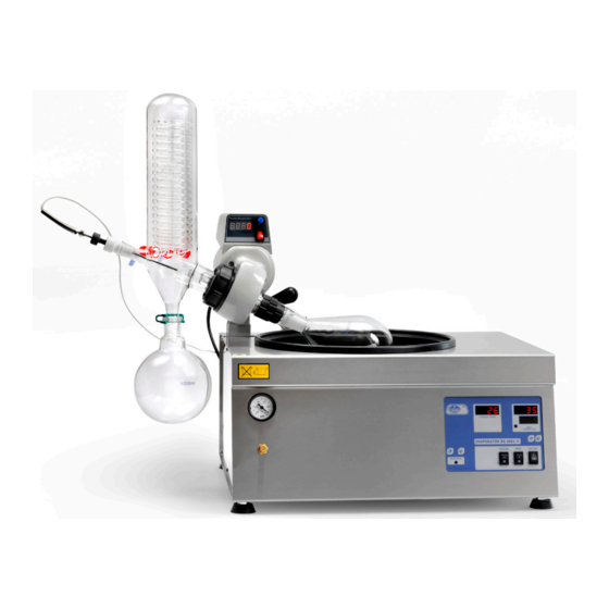
EVAPORADOR ROTATIVO RS 3001-V
ROTATORY EVAPORATOR RS 3001-V
COD 6003001
J
.P. SELECTA s.a.u.
Autovía A-2 Km 585.1 Abrera 08630 (Barcelona) España
Tel 34 937 700 877 Fax 34 937 702 362
e-mail: selecta@jpselecta.es - website: http://www.grupo-selecta.com
Advertisement
Table of Contents

Related Manuals for J.P. SELECTA RS 3001-V


Summary of Contents for J.P. SELECTA RS 3001-V
- Page 1 MANUAL DE INSTRUCCIONES CODIGO 80370 REV 0 Juliol/2018 (Sujetas a modificaciones sin previo aviso) Pag.: 1 EVAPORADOR ROTATIVO RS 3001-V ROTATORY EVAPORATOR RS 3001-V COD 6003001 .P. SELECTA s.a.u. Autovía A-2 Km 585.1 Abrera 08630 (Barcelona) España Tel 34 937 700 877 Fax 34 937 702 362...
-
Page 2: Table Of Contents
INSTRUCTION MANUAL CODE 80370 REV 0 Juliol/2018 (It can be modified without notice) Page: 2 Indice 1 SEGURIDAD ..............................3 2 INFORMACIÓN GENERAL ..........................4 3 ESPECIFICACIONES TÉCNICAS ........................4 4 LISTA DE EMBALAJE .............................5 5 INSTALACIÓN Y MONTAJE DEL EQUIPO ......................6 6 COMPONENTES ............................10 7 FUNCIONAMIENTO .............................14 8 FUNCIONES ADICIONALES.........................15 9 MANTENIMIENTO Y LIMPIEZA ........................15... -
Page 3: Seguridad
MANUAL DE INSTRUCCIONES CODIGO 80370 REV 0 Juliol/2018 (Sujetas a modificaciones sin previo aviso) Pag.: 3 1 SEGURIDAD El equipo incluye las medidas de seguridad adecuadas. A lo largo de este manual se indican las situaciones de riesgo que deben respetarse. 1.1 Iconos de seguridad Identifican las situaciones de riesgo y las medidas de seguridad que deben tomarse. -
Page 4: Información General
INSTRUCTION MANUAL CODE 80370 REV 0 Juliol/2018 (It can be modified without notice) Page: 4 2 INFORMACIÓN GENERAL 2.1 Manipular el paquete con cuidado. Desembalarlo y comprobar que el contenido coincide con lo indicado en el apartado de la “Lista de embalaje”. Si se observa algún componente dañado o la ausencia de alguno, avisar rápidamente al distribuidor. -
Page 5: Lista De Embalaje
MANUAL DE INSTRUCCIONES CODIGO 80370 REV 0 Juliol/2018 (Sujetas a modificaciones sin previo aviso) Pag.: 5 4 LISTA DE EMBALAJE Contenido estándar del paquete El equipo estándar consta de los siguientes componentes: Nº Descripción Pos. 6003001 Evaporador rotativo 0100146 GRIFO ENTRADA 0100160 TUBO PTFE GRIFO ENTRADA 0100145 REFRIGERANTE 1001098 PINZA MATRAZ RECEPTOR... -
Page 6: Instalación Y Montaje Del Equipo
INSTRUCTION MANUAL CODE 80370 REV 0 Juliol/2018 (It can be modified without notice) Page: 6 5 INSTALACIÓN Y MONTAJE DEL EQUIPO • Situe el aparato cerca de una toma de corriente adecuado a su consumo sobre una superficie plana (nivelada) y suficientemente robusta para soportar el peso del equipo. - Page 7 MANUAL DE INSTRUCCIONES CODIGO 80370 REV 0 Juliol/2018 (Sujetas a modificaciones sin previo aviso) Pag.: 7 5. Monte las juntas tal y como se muestra en la foto. Coloque primero la junta gris. 6. Luego coloque la junta marrón. 7. Vista del conjunto de juntas montado. 8.
- Page 8 INSTRUCTION MANUAL CODE 80370 REV 0 Juliol/2018 (It can be modified without notice) Page: 8 12. Monte el conjunto refrigerante (3) usando la rosca negra (6) en el cabezal completo (10). 13. Vista del conjunto una vez montado. 14. Instale el matraz receptor (9) con la pinza (4) insertándola a presión. 15.
- Page 9 MANUAL DE INSTRUCCIONES CODIGO 80370 REV 0 Juliol/2018 (Sujetas a modificaciones sin previo aviso) Pag.: 9 19. Monte la cinta de sujeción a la varilla. 20. Abrace el cristal refrigerante (3) con la cinta. 21. Detalle de como debe quedar el montaje. 22.
-
Page 10: Componentes
INSTRUCTION MANUAL CODE 80370 REV 0 Juliol/2018 (It can be modified without notice) Page: 10 6 COMPONENTES 1- Grifo Entrada 2- Tubo PTFE Grifo Entrada 3- Refrigerante 4- Pinza Matraz Receptor 5- Juego 3 tapones c/oliva 6- Rosca Negra Refrigerante 7- Muelle para Rosca Negra 8- Juego Juntas Vacío y Sellado Matraz Receptor 1000ml (de Pera) - Page 11 MANUAL DE INSTRUCCIONES CODIGO 80370 REV 0 Juliol/2018 (Sujetas a modificaciones sin previo aviso) Pag.: 11 15- Conector sonda temperatura 16- Conector alimentación motor reductor (10) 17- Cable conexión a la red eléctrica 18- Cubeta de calefacción .P. SELECTA s.a.u. Autovía A-2 Km 585.1 Abrera 08630 (Barcelona) España Tel 34 937 700 877 Fax 34 937 702 362 e-mail: selecta@jpselecta.es - website: http://www.grupo-selecta.com...
- Page 12 INSTRUCTION MANUAL CODE 80370 REV 0 Juliol/2018 (It can be modified without notice) Page: 12 19- Entrada agua serpentín refrigeración 20- Salida agua serpentín refrigeración 21- Conexión de la bomba de vacío 22- Vacuómetro 23- Válvula ajuste vacío 24- Salida aire vacío 25- Válvula de desagüe 26- Panel de mandos 27- Filtro 0,2µm.
- Page 13 MANUAL DE INSTRUCCIONES CODIGO 80370 REV 0 Juliol/2018 (Sujetas a modificaciones sin previo aviso) Pag.: 13 Termómetro lector Regulador de temperatura de cubeta calefacción Tecla descender el conjunto rotor Tecla elevar el conjunto rotor Interruptor de marcha de bomba vacío Interruptor de la calefacción Interruptor general Teclas de ajuste de la temperatura de trabajo de la cubeta...
-
Page 14: Funcionamiento
INSTRUCTION MANUAL CODE 80370 REV 0 Juliol/2018 (It can be modified without notice) Page: 14 7 FUNCIONAMIENTO 7.1 Operación 1. Realice las operaciones del apartado «Instalación». 2. Compruebe que la válvula de vaciado (20) está correctamente cerrada. 3. Compruebe que la válvula de rotura de vacío está cerrada. 4. -
Page 15: Funciones Adicionales
MANUAL DE INSTRUCCIONES CODIGO 80370 REV 0 Juliol/2018 (Sujetas a modificaciones sin previo aviso) Pag.: 15 8 FUNCIONES ADICIONALES Para trabajar en modo Adición de productos durante la destilación, es necesario colocar la válvula de entrada de líquidos (1) en lugar de la sonda de temperatura antes de empezar el proceso de trabajo. -
Page 16: Problemas Y Soluciones
INSTRUCTION MANUAL CODE 80370 REV 0 Juliol/2018 (It can be modified without notice) Page: 16 10 PROBLEMAS Y SOLUCIONES Descripción Causa Resolución No calienta Temperatura de trabajo Revise el capítulo “7.Funcio- por debajo de la tem- namiento” para seleccionar la peratura ambiente temperatura La resistencia está... - Page 17 MANUAL DE INSTRUCCIONES CODIGO 80370 REV 0 Juliol/2018 (Sujetas a modificaciones sin previo aviso) Pag.: 17 ENGLISH VERSION .P. SELECTA s.a.u. Autovía A-2 Km 585.1 Abrera 08630 (Barcelona) España Tel 34 937 700 877 Fax 34 937 702 362 e-mail: selecta@jpselecta.es - website: http://www.grupo-selecta.com...
-
Page 18: Safety
INSTRUCTION MANUAL CODE 80370 REV 0 Juliol/2018 (It can be modified without notice) Page: 18 1 SAFETY The equipment includes the appropriate safety features. Risky situations that must be respected are indicated in this manual. 1.1 Safety Icons They identify risky situations and safety measures that should be taken. The icons make reference to the paragraph marked with a grey line. -
Page 19: General Information
2.4 If you have any doubts or enquiries, please contact with your supplier or J.P. Selecta’s technical service. 2.5 IMPORTANT! J.P. SELECTA WILL NOT ACCEPT ANY EQUIPMENT TO BE REPAIRED IF IT IS NOT DULY CLEANED. 2.6 If any modification, elimination or lacking in maintenance of any device of the equipment by the user transgress the directive 89/655/CEE, the manufacturer is not responsible for the damage that can occur. -
Page 20: Packing List
INSTRUCTION MANUAL CODE 80370 REV 0 Juliol/2018 (It can be modified without notice) Page: 20 4 PACKING LIST The standard equipment is compound by the following parts: Descriptipn Pos. 6003001 ROTATORY EVAPORATOR 0100146 GLASS FEEDING VALVE 0100160 PTFE FEEDING PIPE 0100145 GLASS CONDENSER 1001098 CLAMP FOR RECEIVING FLASK 0100161 3 STOPPERS SET W/OLIVE... -
Page 21: Installation & Assembly
MANUAL DE INSTRUCCIONES CODIGO 80370 REV 0 Juliol/2018 (Sujetas a modificaciones sin previo aviso) Pag.: 21 5 INSTALLATION & ASSEMBLY • Place the equipment near a plug suitable to its amperage on a surface flat and levelled and strong enough to support its weight. •... - Page 22 INSTRUCTION MANUAL CODE 80370 REV 0 Juliol/2018 (It can be modified without notice) Page: 22 5. Mount the gaskets as shown in the picture. Place the grey gasket first. 6. Then install the brown one. 7. View of the joint assembly. 8.
- Page 23 MANUAL DE INSTRUCCIONES CODIGO 80370 REV 0 Juliol/2018 (Sujetas a modificaciones sin previo aviso) Pag.: 23 12. Fit the refrigerant assembly (3) in the angular reduction motor (10). 13. View of the assembly once mounted. 14. Install the receiving flask (9) with the clamp (4) by inserting it under pres- sure.
- Page 24 INSTRUCTION MANUAL CODE 80370 REV 0 Juliol/2018 (It can be modified without notice) Page: 24 19. Mount the rod fastening tape. 20. Hook the refrigerant glass (3) with the tape. 21. Detail of how the assembly should look like. 22. General view of the whole assembly. .P.
-
Page 25: Components
MANUAL DE INSTRUCCIONES CODIGO 80370 REV 0 Juliol/2018 (Sujetas a modificaciones sin previo aviso) Pag.: 25 6 COMPONENTS 1- Glass Feeding Valve 2- PTFE Feeding Pipe 3- Glass Condenser 4- Clamp for Receiving Flask 5- Three stoppers set w/olive 6- Lock Nut Condenser 7- Circlip Lock Nut Condenser 8- Set Gaskets Vacuum &... - Page 26 INSTRUCTION MANUAL CODE 80370 REV 0 Juliol/2018 (It can be modified without notice) Page: 26 15- Temperature probe plug 16- Reduction motor power plug (10) 17- Power supply cord 18- Heating tray .P. SELECTA s.a.u. Autovía A-2 Km 585.1 Abrera 08630 (Barcelona) España Tel 34 937 700 877 Fax 34 937 702 362 e-mail: selecta@jpselecta.es - website: http://www.grupo-selecta.com...
- Page 27 MANUAL DE INSTRUCCIONES CODIGO 80370 REV 0 Juliol/2018 (Sujetas a modificaciones sin previo aviso) Pag.: 27 19- Coil cooling water inlet 20- Coil cooling water outlet 21- Vacuum pump connection 22- Vacuum meter 23- Vacuum adjustment valve 24- Vacuum air outlet 25- Drainage valve 26- Control Panel 27- Filter 0,2µm.
- Page 28 INSTRUCTION MANUAL CODE 80370 REV 0 Juliol/2018 (It can be modified without notice) Page: 28 Temperature display Heating Tray Temperature regulator Lower the rotor assembly key Raise the rotor assembly key Vacuum pump switch Heating switch Main switch Adjustment keys for the tray’s temperature Rotation speed display Rotation speed adjustment knob Motor switch...
-
Page 29: Operation
MANUAL DE INSTRUCCIONES CODIGO 80370 REV 0 Juliol/2018 (Sujetas a modificaciones sin previo aviso) Pag.: 29 7 OPERATION 7.1 Operatiom 1. Follow the instructions of the «Installation» chapter. 2. Check that the emptying valve (20) is correctly closed. 3. Check that the vacuum breaking valve is closed. 4. -
Page 30: Additional Funtions
INSTRUCTION MANUAL CODE 80370 REV 0 Juliol/2018 (It can be modified without notice) Page: 30 8 ADDITIONAL FUNTIONS To work in the Addition of products during distillation mode, it is necessary to connect the liquids inlet valve (1) instead of the temperature probe before starting the working process. -
Page 31: Troubleshooting
MANUAL DE INSTRUCCIONES CODIGO 80370 REV 0 Juliol/2018 (Sujetas a modificaciones sin previo aviso) Pag.: 31 10 TROUBLESHOOTING Description Cause Resolution It does not heat Working temperature Check chapter “7.Opera- lower than room tem- tion” to select the temper- perature ature Resistance is melted Contact with the technical... - Page 32 INSTRUCTION MANUAL CODE 80370 REV 0 Juliol/2018 (It can be modified without notice) Page: 32 .P. SELECTA s.a.u. Autovía A-2 Km 585.1 Abrera 08630 (Barcelona) España Tel 34 937 700 877 Fax 34 937 702 362 e-mail: selecta@jpselecta.es - website: http://www.grupo-selecta.com...
Need help?
Do you have a question about the RS 3001-V and is the answer not in the manual?
Questions and answers