
Subscribe to Our Youtube Channel
Related Manuals for Panduit ATLONA AT-HDR-CAT-4ED


Summary of Contents for Panduit ATLONA AT-HDR-CAT-4ED
- Page 1 4K / HDR HDMI to HDBaseT HDMI 1 x 4 Extended Distance Distribution Amplifier Atlona Manuals AT-HDR-CAT-4ED Distribution Amplifiers...
- Page 2 Version Information Version Release Date Notes Jan 2023 Initial release AT-HDR-CAT-4ED...
- Page 3 Sales, Marketing, and Customer Support Main Office International Headquarters Atlona Incorporated Atlona International AG 70 Daggett Drive Tödistrasse 18 San Jose, CA 95134 8002 Zürich United States Switzerland Office: +1.408.962.0515 Office: +41.43.508.4321 Sales and Customer Service Hours Monday - Friday: 6:00 a.m. - 4:30 p.m. (PST) Sales and Customer Service Hours Monday - Friday: 09:00 - 17:00 (UTC +1) https://atlona.com/...
- Page 4 Safety and Certification 9. Do not defeat the safety purpose of a polarized CAUTION or grounding-type plug. A polarized plug has two RISK OF ELECTRIC SHOCK blades with one wider than the other. A grounding DO NOT OPEN type plug has two blades and a third grounding CAUTION: TO REDUCT THE RISK OF prong.
-
Page 5: Table Of Contents
Table of Contents Introduction Features Package Contents Panel Description Front Panel Back Panel Connection Instructions Connection Diagram IP Configuration Setting the IP Mode Setting the IP Address Using Commands Auto IP (APIPA) Mode Device Operation LED Indicators Logging in to the Web Server Login Registration Logging in after Registration Locking / Unlocking the Front Panel... - Page 6 Table of Contents Appendix Updating the Firmware Using the Web Server Using USB Default Settings Specifications AT-HDR-CAT-4ED...
-
Page 7: Introduction
Introduction The Atlona AT-HDR-CAT-4ED is a high dynamic range (HDR) distribution amplifier with one HDMI® input and four extended distance HDBaseT™ outputs. Each output transmits 4K/UHD video @ 60 Hz with 4:4:4 chroma sampling plus support for HDR formats, multi-channel audio, Ethernet, control signals, and power up to 330 ft. -
Page 8: Panel Description
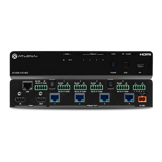
Panel Description Front Panel HDMI HDBaseT LOCK INT LEARN AT-HDR-CAT-4ED POWER EDID RS-232 AUDIO OUT RS-232 RS-232 RS-232 RS-232 RX TX RX TX RX TX RX TX RX TX HDMI Indicators Displays the status of the HDMI IN and HDMI OUT This LED indicator will be blue when the unit is using ports. -
Page 9: Back Panel
HDMI HDBaseT LOCK INT LEARN Panel Description Back Panel AT-HDR-CAT-4ED POWER EDID RS-232 AUDIO OUT RS-232 RS-232 RS-232 RS-232 RX TX RX TX RX TX RX TX RX TX HDMI HDBaseT OUT DC 48V HDMI IN RS-232/IR 1 - 4 Connect an HDMI cable from this port to a source Connect a control system or other DTE device to device. -
Page 10: Connection Instructions
Installation Connection Instructions 1. Connect an HDMI cable from a source to the HDMI IN port. 2. Connect an HDMI cable from the HDMI OUT port to a local display. 3. Connect up to four category cables from the HDBaseT OUT ports to compatible PoE-capable receivers. Refer to the table below for information on maximum cable length and supported resolutions. -
Page 11: Connection Diagram
Installation Connection Diagram AT-HDR-CAT-4ED LE AR IN T se T W ER AT-HDR-EX-100CEA-RX T- 4E D R- AT -H AT-HDR-EX-100CEA-RX Display AT-HDR-EX-100CEA-RX AT-HDR-EX-100CEA-RX Display Display Display Display AT-HDR-CAT-4ED... -
Page 12: Ip Configuration
Installation IP Configuration The AT-HDR-CAT-4ED is shipped with DHCP enabled. Once connected to a network, the DHCP server (if available), will automatically assign an IP address to the unit. If the AT-HDR-CAT-4ED is unable to detect a DHCP server within 15 seconds, then the unit will use a self-assigned IP address within the range of 169.254.xxx.xxx/16. -
Page 13: Setting The Ip Address Using Commands
Installation Using the Web Server The IP mode of the AT-HDR-CAT-4ED can also be set using the built-in web server. In order to access the web server, the IP address of the AT-HDR-CAT-4ED must be known. Refer to Logging in to the Web Server (page 16) for more information. -
Page 14: Auto Ip (Apipa) Mode
Installation • Setting DHCP mode 1. Connect to the AT-HDR-CAT-4ED using RS-232 or Telnet. 2. At the command line, execute the IPDHCP command using the on argument, as shown. All characters are case-sensitive. IPDHCP on Once DHCP is enabled, the unit will be assigned an IP address by the DHCP server (if present). Auto IP (APIPA) Mode If the AT-HDR-CAT-4ED is unable to detect a DHCP server within 15 seconds, when set to DHCP mode, then the unit will use a self-assigned IP address within the IPv4 address block 169.254.xxx.xxx/16. -
Page 15: Device Operation
Device Operation LED Indicators The LED indicators on the front/back of the unit provide basic information on the current status of the AT-HDR-CAT- 4ED. Description POWER Blue Unit is powered and in normal operating mode. Unit is in standby mode. •... -
Page 16: Logging In To The Web Server
Device Operation Logging in to the Web Server Most of the AT-HDR-CAT-4ED operation is handled through the built-in web server. In order to access the web server, the IP address of the unit must be known. Refer to IP Configuration (page 12) for more information. -
Page 17: Logging In After Registration
Device Operation Logging in after Registration 1. Launch the desired web browser and enter the IP address of the AT-HDR-CAT-4ED in the address bar. 2. Enter the correct username and password in the respective fields. 3. Click the Submit button. 4. -
Page 18: Locking / Unlocking The Front Panel
Device Operation Locking / Unlocking the Front Panel The buttons on the front panel can be locked or unlocked. Locking the front-panel buttons prevents accidental pressing of the buttons, which may occur when the unit is mounted in a rack environment. Locking and unlocking of the front-panel buttons is managed through the web server or by executing the Lock and Unlock API commands. -
Page 19: Edid Management
Device Operation EDID Management The AT-HDR-CAT-4ED provides two EDID modes: INT and LEARN. The default EDID mode is INT mode. In this mode, the AT-HDR-CAT-4ED will automatically create an EDID based on the capabilities of all connected displays. INT mode is recommended for the best results when the capabilities of all connected displays are unknown. INT mode can also be used to select any of 9 EDID presets. -
Page 20: Learning The Edid Using The Web Server
Device Operation Learning the EDID using the Web Server 1. Follow steps 1 through 3 under Learning an EDID using the Front Panel (page 19). 2. Log in to the web server. 3. Click EDID in the menu bar. 4. Click the EDID mode drop-down list and select LEARN. 5. -
Page 21: Selecting Edid Presets
Device Operation Selecting EDID Presets The AT-HDR-CAT-4ED comes with a default EDID plus 8 pre-programmed EDID selections. When selecting the default or one of the pre-programmed EDID selections, the EDID mode must be set to INT (internal) mode. Available EDID selections are presented in the table below. All resolutions are 60 Hz. EDID Description Connected Display... -
Page 22: Changing Login Credentials
Device Operation Changing Login Credentials The AT-HDR-CAT-4ED allows both the username and password to be changed. These credentials apply to both the built-in web server and Telnet sessions. NOTE: When creating passwords, special characters are not supported. Password fields will always be masked for security purposes. -
Page 23: Controlling Audio Output
Device Operation Controlling Audio Output The AT-HDR-CAT-4ED features a separate AUDIO OUT port on the rear panel. This port provides de-embedding and conversion of two-channel LPCM audio streams to analog audio. Audio output volume can be controlled using API commands or the built-in web server. IMPORTANT: The AT-HDR-CAT-4ED will only de-embed two-channel LPCM audio. -
Page 24: De-Embedding Audio
Device Operation De-Embedding Audio 1. Log in to the web server. 2. Click A/V Settings in the menu bar. 3. Click Analog Output toggle switch and set to the ON position. To mute the audio output on the AUDIO OUT port, click this toggle switch to the OFF position. -
Page 25: Rs-232 Control
Device Operation RS-232 Control The AT-HDR-CAT-4ED provides two methods of RS-232 control: Pass-through mode and control mode. The MASTER RS-232 / IR port, allows the unit to be directly controlled using a control system. In addition four pass- through RS-232 / IR ports allow sink devices, at the viewing location, to be controlled using a control system. 1 2 3 4 5 RS-232 is serial data protocol that allows Data Terminal Equipment (DTE) devices, such a computer or control system, to communicate with Data Communication Equipment (DCE) devices, such as the AT-HDR-CAT-4ED or a... - Page 26 Device Operation 1. Identify the DE-9 connector that will be attached to the control system or computer (DCE) equipment. 2. Remove the DE-9 connector at the opposite end of the cable with wire cutters. 3. Remove at least 1” of the cable insulation to expose each of the nine wires. HDMI HDBaseT 4.
-
Page 27: Pass-Through Mode
Device Operation Pass-through mode In pass-through mode, RS-232 commands are passed-through the AT-HDR-CAT-4ED, transmitted over HDBaseT to a receiver unit, and then to the display (sink) device. Note that each RS-232 / IR port is assigned to an HDBaseT OUT port. This assignment is fixed and cannot be changed, as shown in the table below. RS-232 / IR Port HDBaseT Port RS-232 / IR 1... -
Page 28: Control Mode
Device Operation Control mode In control mode, the MASTER RS-232 / IR port is used to directly control the AT-HDR-CAT-4ED using a control system. 1. Launch a web browser and log in to the web server. 2. Connect the RS-232 cable between the control system and the MASTER RS-232 / IR port on the AT-HDR-CAT- 4ED. -
Page 29: Ir Control
Device Operation IR Control IR can be used to control either source devices at the headend or devices connected to the receiver endpoint, such as a display. Note that the MASTER RS-232 / IR port does not support IR control. Each RS-232 / IR port is assigned to an HDBaseT OUT port. -
Page 30: Controlling Source Devices
Device Operation Controlling Source Devices 1. Remove at least 3/16” (5 mm) of insulation from the RX and GND wires of the emitter. 2. Locate the included 5-pin captive screw block and open each of the terminals by turning the screws counter- clockwise, using a small regular screwdriver. -
Page 31: Power Button Modes
Device Operation Power Button Modes The main function of the POWER button on the front panel is to toggle the AT-HDR-CAT-4ED between standby and normal operating mode. This is the default mode. However, this button can also be defined to send CEC power- on and power-off commands, over HDBaseT, to the display (sink) devices. -
Page 32: Powering Sink Devices
Device Operation Powering Sink Devices This section provides information on how to power-on / power-off the display (sink) device, using the POWER button. CEC* power-on / power-off commands are transmitted over both HDBaseT OUT ports, as well as the pass- through HDMI OUT port. - Page 33 Device Operation 6. Test the CEC power-on and power-off commands by clicking the ON and OFF buttons, near the bottom of the page. 7. Press the POWER button on the front panel to power-on or power-off the display. Note that the power state of the AT-HDR-CAT-4ED will be unaffected.
-
Page 34: Powering Sinks And The At-Hdr-Cat-4Ed
Device Operation Powering Sinks and the AT-HDR-CAT-4ED In this mode, the POWER button will power-on / power-off the unit and the connected displays. CEC* power-on / power-off commands are transmitted over both HDBaseT OUT ports. 1. Make the proper connections by following steps 1 and 2, under Powering Sink Devices (page 32). -
Page 35: Setting The Host Name
Device Operation Setting the Host Name By default, the AT-HDR-CAT-4ED is assgned a hostname, which is constructed as follows: CAT-4ED-[last six digits of MAC address] For example, a default hostname might look like this: CAT-4ED-060709. This value can be changed to easily identify the AT-HDR-CAT-4ED within the Velocity with Integrated AMS or a network. -
Page 36: Resetting To Factory-Default Settings
Device Operation Resetting to Factory-Default Settings The following procedure will reset the AT-HDR-CAT-4ED to factory-default settings. The network IP mode will be set to DHCP mode. Using the Web Server 1. Launch a web browser and log in to the web server. Refer to Logging in to the Web Server (page 16). - Page 37 Device Operation Using the Front Panel 1. Press and hold both the POWER and EDID buttons for 15 seconds. 2. Release both POWER and EDID buttons once the front panel LED indicators turn on. After two seconds, the front panel LED indicators will turn off. POWER button EDID button HDMI...
-
Page 38: Configuration And Management Interfaces
Configuration and Management Interfaces Web Server The AT-HDR-CAT-4ED includes a built-in web server. Atlona recommends that the web server be used to set up the AT-HDR-CAT-4ED, as it provides intuitive management of all features. Refer to Logging in to the Web Server (page for more information. -
Page 39: Login Page
Configuration and Management Interfaces Login page This page is displayed when the IP address of the AT-HDR-CAT-4ED is entered in the address bar of a web browser. Username Enter the username in this field. Password Enter the password in this field. Submit Click this button to log in. -
Page 40: Info Page
Configuration and Management Interfaces Info page Info Model Name The model SKU of this product. Software Version The version of firmware that the AT-HDR-CAT-4ED is running. Always make sure to check the AT-HDR-CAT-4ED product page, on the Atlona web site, for the latest version of firmware. Output VALENS Version The version of firmware on the HDBaseT chip for HDBaseT OUT 1 - HDBaseT OUT 4. -
Page 41: A/V Settings Page
Configuration and Management Interfaces A/V Settings page Settings HDCP Click this drop-down list to select the HDCP reporting mode. Setting Description Compliant Allows the source device to send HDCP content to an HDCP-compliant display. This is the default setting. Non-compliant Will attempt to force the source device to ignore detection of HDCP-compliant displays, allowing non-HDCP content to be transmitted from the souce (if possible). - Page 42 Configuration and Management Interfaces RS-232 page RS-232 RS-232 Parameter Setting Click each of these drop-down boxes to select the desired baud rate, data bits, parity bit, and stop bit for the MASTER RS-232 / IR port. Setting Description Baud rate Sets the baud rate.
-
Page 43: Edid Page
Configuration and Management Interfaces EDID page EDID EDID lock Click this toggle to switch the EDID lock mode. When set to the LOCK position, the LOCK LED indicator on the front panel will glow solid blue. Note that in this mode, all front-panel buttons are locked. EDID mode Click this drop-down list to select the desired EDID mode. -
Page 44: Config Page
Configuration and Management Interfaces Config page Configuration Old Username Enter the current username in this field. Old Password Enter the current password in this field. New Username Enter the new username in this field. New Password Enter the new password in this field. Confirm New Password Verify the new password by retyping it in this field. -
Page 45: Hdbt Page
Configuration and Management Interfaces HDBT page HDBaseT Channel Cable Test HDBaseT Zone Click this drop-down list to select the desired HDBaseT output to be tested. Setting Description Setting Description Output 1 HDBaseT OUT 1 Output 3 HDBaseT OUT 3 Output 2 HDBaseT OUT 2 Output 3 HDBaseT OUT 4... -
Page 46: System Page
Configuration and Management Interfaces System page Network MAC address Displays the MAC address of the AT-HDR-CAT-4ED. IP Mode Click this toggle to set the IP mode of the AT-HDR-CAT-4ED. Setting Description DHCP Uses an available DHCP server to assign an IP address. STATIC IP Allows the IP address, subnet mask, and gateway IP address to be entered manually. - Page 47 Configuration and Management Interfaces Telnet Timeout Click this drop-down list to select the timeout interval, in seconds, before the Telnet connection is automatically closed after no activity. Range: 1 to 3600 (seconds). Broadcast This option determines whether or not systems changes are announced over TCP/IP connections to any listening devices.
- Page 48 Configuration and Management Interfaces Power button mode Click this drop-down list to select the desired function of the power button. Refer to Power Button Modes (page for more information. Setting Description DA standby Pressing the POWER button will toggle the AT-HDR-CAT-4ED between standby mode and normal operating mode.
-
Page 49: Appendix
Appendix Updating the Firmware Updating the firmware can be completed using either the USB interface or the web server. Atlona recommends using the web server for updating the MCU firmware. However, if a network connection is not available, the AT-HDR- CAT-4ED firmware can be updated using a USB-A to USB-C cable. -
Page 50: Using Usb
Appendix Using USB Required items: • AT-HDR-CAT-4ED • Computer containing the firmware file. • USB-A to USB-C cable 1. Disconnect power from the AT-HDR-CAT-4ED. 2. Press and hold the EDID button while connecting power to the AT-HDR-CAT-4ED. 3. Release the EDID button. The POWER button will glow solid red, indicating that the AT-HDR-CAT-4ED is in update mode. -
Page 51: Default Settings
Appendix Default Settings The following tables list the factory-default settings for the AT-HDR-CAT-4ED. Feature Setting Value A/V Settings HDCP Compliant Analog Output Analog Output Volume RS-232 Baud rate 115200 Data bit Parity None Stop bit EDID EDID lock UNLOCK EDID mode INT EDID settings Connected Display System... -
Page 52: Specifications
Appendix Specifications Video Signal Input - HDMI Output - HDMI / HDBaseT Copy Protection HDCP 2.2 Pixel Clock 600 MHz UHD/HD/SD 4096x2160 (DCI) @ 24/25/30/50/60 Hz 720x576p @ 50 Hz 3840x2160 (UHD) @ 24/25/30/50/60 Hz 720x576i @ 25/50 Hz 1920x1080p @ 720x480p @ 60 Hz 23.97/24/25/29.97/30/50/60 Hz 640x480p @ 60 Hz... - Page 53 Appendix RS-232 Port 5 x 5-pin captive screw Unit and external device control and configuration Baud Rates 2400, 4800, 9600, 19200, 38400, 57600, 115200 Data Flow Bidirectional Port 5 x 5-pin captive screw Pass-through from control system to sink device Pass-through from viewing location to source Frequency Range 30 kHz to 60 kHz...
- Page 54 Appendix Dimensions (H x W x D) Inches Millimeters Unit 1.73 x 8.64 x 10 44 x 219.5 x 254 Power Supply 1.3 x 2.24 x 5.35 33 x 57 x 136 (AT-PS-48208-C) Weight Pounds Kilograms Device 3.75 Certification Device CE, RoHS, FCC Power Supply CE, FCC, UL, CUL, TUV-GS, CB, PSE, CCC...
- Page 55 International atlona.com 408.962.0515 41.43.508.4321 • • 35308-R1...
Need help?
Do you have a question about the ATLONA AT-HDR-CAT-4ED and is the answer not in the manual?
Questions and answers