
Related Manuals for Panduit Atlona AT-UHD-CAT-4


Summary of Contents for Panduit Atlona AT-UHD-CAT-4
- Page 1 4K / UHD HDMI to HDBaseT Distribution Amplifier Atlona Manuals AT-UHD-CAT-4 Distribution Amplifiers...
- Page 2 Version Information Version Release Date Notes Mar 2019 New format Mar 2021 Included instructions for Updating the Valens Firmware (page 41). AT-UHD-CAT-4...
- Page 3 Welcome to Atlona! Thank you for purchasing this Atlona product. We hope you enjoy it and will take an extra few moments to register your new purchase. Registration only takes a few minutes and protects this product against theft or loss. In addition, you will receive notifications of product updates and firmware.
- Page 4 Atlona, Inc. (“Atlona”) Limited Product Warranty Coverage Atlona warrants its products will substantially perform to their published specifications and will be free from defects in materials and workmanship under normal use, conditions and service. Under its Limited Product Warranty, Atlona, at its sole discretion, will either: •...
- Page 5 Atlona, Inc. (“Atlona”) Limited Product Warranty • Damage, deterioration or malfunction resulting from the installation or removal of this product from any installation, any unauthorized tampering with this product, any repairs attempted by anyone unauthorized by Atlona to make such repairs, or any other cause which does not relate directly to a defect in materials and/or workmanship of this product.
- Page 6 Safety and Certification 9. Do not defeat the safety purpose of a polarized CAUTION or grounding-type plug. A polarized plug has two RISK OF ELECTRIC SHOCK blades with one wider than the other. A grounding DO NOT OPEN type plug has two blades and a third grounding CAUTION: TO REDUCT THE RISK OF prong.
-
Page 7: Table Of Contents
Table of Contents Introduction Features Package Contents Panel Description Installation Connection Instructions Connection Diagram IP Configuration Setting the IP Mode Setting the IP Address Using Commands Setting the IP Address using the Web GUI Basic Operation LED Indicators Locking the Front Panel Using the Front Panel Using the web GUI EDID Management... -
Page 8: Introduction
Introduction The Atlona AT-UHD-CAT-4 is a 4K/UHD HDMI to HDBaseT distribution amplifier featuring pass-through HDMI input connections, four HDBaseT outputs and display control capability. Each output transmits AV and control signals up to 230 ft. (70 m) @ 1080p and 130 ft. (40 m) @ 4K/UHD. Features include 4K/UHD @ 60 Hz with 4:2:0 color subsampling, HDCP 2.2 compliance, EDID management, and PoE for powering remote receivers. -
Page 9: Panel Description
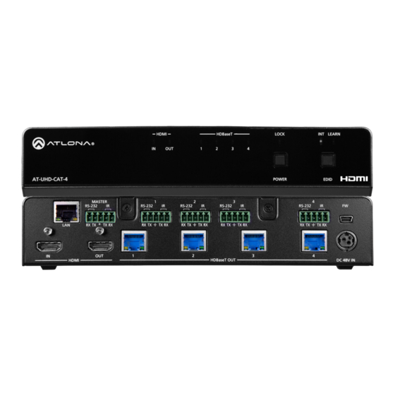
Panel Description HDMI HDBaseT LOCK INT LEARN HDMI HDBaseT LOCK INT LEARN AT-UHD-CAT-4 POWER EDID AT-UHD-CAT-4 POWER EDID MASTER MASTER RS-232 RS-232 RS-232 RS-232 RS-232 RS-232 RS-232 RS-232 RS-232 RS-232 HDMI HDBaseT OUT DC 48V HDMI HDBaseT OUT DC 48V HDMI Indicators Displays the status of the HDMI IN and HDMI OUT Connect an Ethernet cable from this port to the... -
Page 10: Installation
Installation Connection Instructions 1. Connect an HDMI cable from a UHD/HD source to the HDMI IN port. 2. Connect an HDMI cable from the HDMI OUT port to a display (sink) device. 3. Connect up to four Ethernet cables from the HDBaseT OUT ports to compatible PoE-capable receivers. Refer to the table below for information on maximum cable length and supported resolutions. -
Page 11: Connection Diagram
Installation Connection Diagram Display LE AR IN T se T W ER -C AT AT -U AT-UHD-CAT-4 Laptop -R X X -7 D -E A T- W ER LI N AT-UHD-EX-70C-RX -R X X -7 D -E A T- W ER LI N AT-UHD-EX-70C-RX -R X... -
Page 12: Ip Configuration
Installation IP Configuration The AT-UHD-CAT-4 is shipped with DHCP enabled. Once connected to a network, the DHCP server (if available), will automatically assign an IP address to the unit. Use an IP scanner, along with the MAC address on the back of the unit, to identify both the unit and its IP address on the network. -
Page 13: Setting The Ip Address Using The Web Gui
Installation 3. Execute the IPStatic command. This command requires three arguments: the desired IP address of the AT-UHD-CAT-4, the subnet mask, and the gateway address. All arguments must be entered in dot-decimal notation. The following is an example: IPStatic 192.168.1.112 255.255.255.0 192.168.1.1 IP address Subnet mask Gateway... -
Page 14: Basic Operation
Basic Operation LED Indicators The LED indicators on both the front of the unit provide basic information on the current status of the AT-UHD-CAT-4. Description POWER Blue Unit is powered and in normal operating mode. Unit is in standby mode. •... -
Page 15: Locking The Front Panel
Basic Operation Locking the Front Panel The buttons on the front panel can be locked or unlocked. Locking the front-panel buttons prevents accidental pressing of the buttons, which may occur when the unit is mounted in a rack environment. Locking and unlocking of the front-panel buttons is managed through the web GUI or by executing the Lock and Unlock API commands. -
Page 16: Edid Management
Basic Operation EDID Management The AT-UHD-CAT-4 provides two EDID modes: INT and LEARN. The default EDID mode is INT mode. In this mode, the AT-UHD-CAT-4 will automatically create an EDID based on the capabilities of all connected displays. INT mode is recommended for the best results when the capabilities of all connected displays are unknown. -
Page 17: Learning The Edid Using The Web Gui
Basic Operation Learning the EDID using the web GUI 1. Follow steps 1 through 3 under Learning an EDID using the Front Panel (page 16). 2. Login to the web GUI. Refer to Introduction to the Web GUI (page 31) for more information. -
Page 18: Selecting Edid Presets
Basic Operation Selecting EDID Presets The AT-UHD-CAT-4 comes with a default EDID plus 16 pre-programmed EDID selections. When selecting the default or one of the pre-programmed EDID selections, the EDID mode must be set to INT (internal) mode. Available EDID selections are presented in the table below. EDID ATL 1280x800 RGB 2CH ATL 1080P 2CH... -
Page 19: Managing Users
Basic Operation Managing Users The AT-UHD-CAT-4 allows the admin user to create, edit, and remove additional TCP/IP users. All users have the same level of access to control the AT-UHD-CAT-4. However, only the admin user is allowed to manage other users. Up to three additional users can be created. -
Page 20: Editing / Deleting Users
Basic Operation Editing / Deleting Users The username and password of a user can be changed using this method. 1. Open the desired web browser and enter the IP address of the AT-UHD-CAT-4. 2. Log in as the admin user with the required credentials. The factory-default username and password for the admin user are listed below: Username: root Password: Atlona... -
Page 21: Advanced Operation
Advanced Operation RS-232 Control The AT-UHD-CAT-4 provides two methods of RS-232 control: Pass-through mode and control mode. The master RS-232 / IR port, allows the unit to be directly controlled using a control system. In addition four pass-through RS- 232 / IR ports allow sink devices, at the viewing location, to be controlled using a control system. 1 2 3 4 5 RS-232 is serial data protocol that allows Data Terminal Equipment (DTE) devices, such a computer or control system, to communicate with Data Communication Equipment (DCE) devices, such as the AT-UHD-CAT-4 or a... -
Page 22: Cable Assembly
Advanced Operation Cable Assembly When connecting a DTE device to a DCE device, a straight-through cable should be used. A straight-through cable is wired in such a way that the pins on one side of the cable are connected to the corresponding pins on the opposite side of the cable, as shown in the table below. -
Page 23: Pass-Through Mode
Advanced Operation Pass-through mode In pass-through mode, RS-232 commands are passed-through the AT-UHD-CAT-4, transmitted over HDBaseT to a receiver unit, and then to the display (sink) device. Note that each RS-232 / IR port is assigned to an HDBaseT OUT port. -
Page 24: Control Mode
Advanced Operation Control mode In control mode, the MASTER RS-232 / IR port is used to directly control the AT-UHD-CAT-4 using a control system. 1. Launch a web browser and login to the web GUI. Refer to Introduction to the Web GUI (page 31) for more information. -
Page 25: Ir Control
Advanced Operation IR Control IR can be used to control either source devices at the headend or devices connected to the receiver endpoint, such as a display. Note that the MASTER RS-232 / IR port does not support IR control. Note that each RS-232 / IR port is assigned to an HDBaseT OUT port. -
Page 26: Controlling Source Devices
Advanced Operation Controlling Source Devices HDMI HDBaseT LOCK INT LEARN 1. Remove at least 3/16” (5 mm) of insulation from the RX and GND wires of the emitter. 2. Locate the included 5-pin captive screw block and open each of the terminals by turning the screws counter- clockwise, using a small regular screwdriver. -
Page 27: Power Button Modes
Advanced Operation Power Button Modes The main function of the POWER button on the front panel is to toggle the AT-UHD-CAT-4 between standby and normal operating mode. This is the default mode. However, this button can also be defined to send CEC power- on and power-off commands, over HDBaseT, to the display (sink) devices. -
Page 28: Powering Sink Devices
Advanced Operation Powering Sink Devices This section provides information on how to power-on / power-off the display (sink) device, using the POWER button. CEC* power-on / power-off commands are transmitted over all HDBaseT OUT ports, as well as the pass- through HDMI OUT port. - Page 29 Advanced Operation 6. Test the CEC power-on and power-off commands by pressing the ON and OFF buttons, near the bottom of the page. 7. Press the POWER button on the front panel to power-on or power-off the display. Note that the power state of the AT-UHD-CAT-4 will be unaffected.
-
Page 30: Powering Sinks And The At-Uhd-Cat-4
Advanced Operation Powering Sinks and the AT-UHD-CAT-4 In this mode, the POWER button will power-on / power-off the unit and the connected displays. CEC* power-on / power-off commands are transmitted over all HDBaseT OUT ports. 1. Make the proper connections by following steps 1 through 4, under Powering Sink Devices (page 28). -
Page 31: The Web Gui
The Web GUI Introduction to the Web GUI The AT-UHD-CAT-4 includes a built-in web GUI. Atlona recommends that the web GUI be used to set up the AT-UHD-CAT-4, as it provides intuitive management of all features. The AT-UHD-CAT-4 is shipped with DHCP enabled. Once connected to a network, the DHCP server will automatically assign an IP address to the unit. -
Page 32: Menu Bar
The Web GUI 7. The Info page will be displayed. 8. Click Logout, on the far-right side of the menu bar, to log out of the web GUI and return to the Login page. Menu Bar The dark-colored bar, near the top of the screen, is the menu bar. When the mouse is moved over each menu element, it will be highlighted in light orange. -
Page 33: Info Page
The Web GUI Info page Model Name The model SKU of this product. Software Version The version of firmware that the AT-UHD-CAT-4 is running. Always make sure to check the AT-UHD-CAT-4 product page, on the Atlona web site, for the latest version of firmware. Output 1 VALENS Version - Output 4 VALENS Version The version of firmware on the HDBaseT chip for each HDBaseT OUT port. -
Page 34: Rs-232 Page
The Web GUI RS-232 page RS-232 Parameter Setting Click each of these drop-down boxes to select the desired baud rate, data bits, parity bit, and stop bit for the MASTER RS-232 / IR port. Setting Description Baud rate Sets the baud rate. The following options are available: 2400, 9600, 19200, 38400, 56000, 57600, 115200. -
Page 35: Edid Page
The Web GUI EDID page EDID lock Click this toggle to switch the EDID lock mode. When set to the LOCK position, the LOCK LED indicator on the front panel will glow solid blue. Note that in this mode, all front-panel buttons are locked. EDID mode Click this drop-down list to select the desired EDID mode. -
Page 36: Config Page
The Web GUI Config page Old Username This field cannot be changed. “root” is the administrator user. Old Password Enter the current password for the “root” username in this field. The default password is “Atlona”. New Username This field cannot be changed. Save Click this button to save all changes. -
Page 37: System Page
The Web GUI System page IP Mode Click this toggle to set the IP mode of the AT-UHD-CAT-4. The default setting is DHCP. Available settings: STATIC IP, DHCP. Enter the IP address of the AT-UHD-CAT-4 in this field. This field will only be available if IP Mode is set to STATIC IP. - Page 38 The Web GUI Power Under normal operation conditions, this toggle is set to ON. Click this toggle to OFF, to place the AT-UHD-CAT-4 in standby mode. The PWOFF and PWON commands can also be used to control the power state. Lock Click to lock or unlock the buttons on the front panel.
-
Page 39: Appendix
Appendix Updating the MCU Firmware Updating the MCU firmware can be completed using either the USB interface or the web GUI. Atlona recommends using the web GUI for updating the MCU firmware. However, if a network connection is not available, the AT-UHD- CAT-4 MCU firmware can be updated using a USB-A to USB mini-B cable. -
Page 40: Using Usb
Appendix Using USB Required items: • AT-UHD-CAT-4 • Computer containing the firmware file. • USB-A to USB mini-B cable 1. Disconnect power from the AT-UHD-CAT-4. 2. Press and hold the POWER button while connecting power to the AT-UHD-CAT-4. 3. Release the POWER button. The POWER button will glow solid red, indicating that the AT-UHD-CAT-4 is in update mode. -
Page 41: Updating The Valens Firmware
Appendix Updating the Valens Firmware Updating the Valens firmware can be completed using either the USB interface or the web GUI. Atlona recommends using the web GUI for updating the Valens firmware. However, if a network connection is not available, the AT-UHD- CAT-4 Valens firmware can be updated using a USB-A to USB mini-B cable. -
Page 42: Using Usb
Appendix Using USB Required items: • AT-UHD-CAT-4 • Computer containing the firmware file. • USB-A to USB mini-B cable 1. Disconnect power from the AT-UHD-CAT-4. 2. Press and hold the EDID button while connecting power to the AT-UHD-CAT-4. 3. Release the EDID button. The POWER button will glow solid red, indicating that the AT-UHD-CAT-4 is in update mode. -
Page 43: Cable Termination
Appendix Cable Termination Atlona recommends EIA/TIA-568-B termination. Connector type and size is very important to ensure extenders work correctly. Always use the matching cable type with the correct RJ45 connector. • CAT5e cables should use only CAT5e RJ45 connectors • CAT6 cables should use only CAT6 connectors •... -
Page 44: Default Settings
Appendix Default Settings The following tables list the factory-default settings for the AT-UHD-CAT-4. Feature Settings RS-232 Baud rate 115200 Data bit Parity None Stop bit EDID EDID lock UNLOCK EDID mode INT EDID settings Config Username (default) root Password (default) Atlona System IP Mode... -
Page 45: Specifications
Appendix Specifications Video HDMI Specification HDMI 1.4, HDCP 2.2 UHD/HD 4096×2160 (DCI)@60/30/24 Hz, 3840×2160 (UHD)@60/50/24/25/30 Hz, 1080p@23.98/24/25/29.97/30 /50/59.94/60 Hz, 1080i@25/29.97/30 Hz, 720p@30/50/59.94/60 Hz VESA 2560×2048, 2560×1600, 2048×1536, 1920×1200, 1680×1050, 1600×1200, 1600×900, 1440×900, 1400×1050, 1366×768, 1360×768, 1280×1024, 1280×800 1280×768, 1152×768, 1024×768, 800×600, 640×480 Color Space YUV, RGB... - Page 46 Appendix Resolution / Distance 4K/UHD - Feet / Meters 1080p - Feet / Meters HDMI IN/OUT CAT5e CAT6/6a/7 Power Consumption 52.80 W Idle Consumption 12.54 W External Power Supply Input: 100 - 240 V AC, 50/60 Hz Output: 48 V DC, 2.08 A Safety CE, FCC, Level IV, cULus, RoHS, RCM, CCC Environmental...
- Page 47 Toll free US Toll free US International International atlona.com 877.536.3976 41.43.508.4321 • • 35229-R3...
Need help?
Do you have a question about the Atlona AT-UHD-CAT-4 and is the answer not in the manual?
Questions and answers